Flue-gas cleaning method and system for waste incineration

A flue gas purification system and waste incineration technology, which is applied in the field of waste incineration flue gas purification and waste incineration flue gas purification system, and can solve problems such as auxiliary machine failure, dust accumulation on the tower wall, wear of the disc and nozzle of the rotary sprayer, etc. , to achieve the effect of facilitating the diffusion of flue gas and high removal efficiency

Inactive Publication Date: 2010-09-15
山东三融环保工程有限公司
View PDF0 Cites 55 Cited by
  • Summary
  • Abstract
  • Description
  • Claims
  • Application Information

AI Technical Summary

Problems solved by technology

Of course, the flue gas within this safe distance will have no chance to touch the liquid absorbent particles, so the flue gas does not undergo deacidification reaction within this range, which is the boundary escape phenomenon that cannot be overcome by the existing rotary spraying process
[0007] If the air flow distribution in the reaction tower is not good, it is easy to cause ash accumulation on the tower wall. Once the plate agglomeration on the tower wall peels off and collapses, it will cause serious blockage to the ash outlet below the reaction tower.
Moreover, because the rotational speed of the rotary sprayer is very high, and the working speed is 12000-18000r / min, wear of the rotary sprayer disc and nozzle, vibration of the rotary sprayer, and failure of auxiliary equipment are prone to occur during operation.
Moreover, with the increase of daily garbage disposal and increasingly stringent pollutant discharge standards, the contradiction between the reaction efficiency of semi-dry scrubber and the reaction product sticking to the wall will become more prominent.

Method used


Image

  • Flue-gas cleaning method and system for waste incineration
  • Flue-gas cleaning method and system for waste incineration
  • Flue-gas cleaning method and system for waste incineration

Examples


Embodiment Construction

[0025] Below in conjunction with accompanying drawing and embodiment the present invention will be described in further detail:

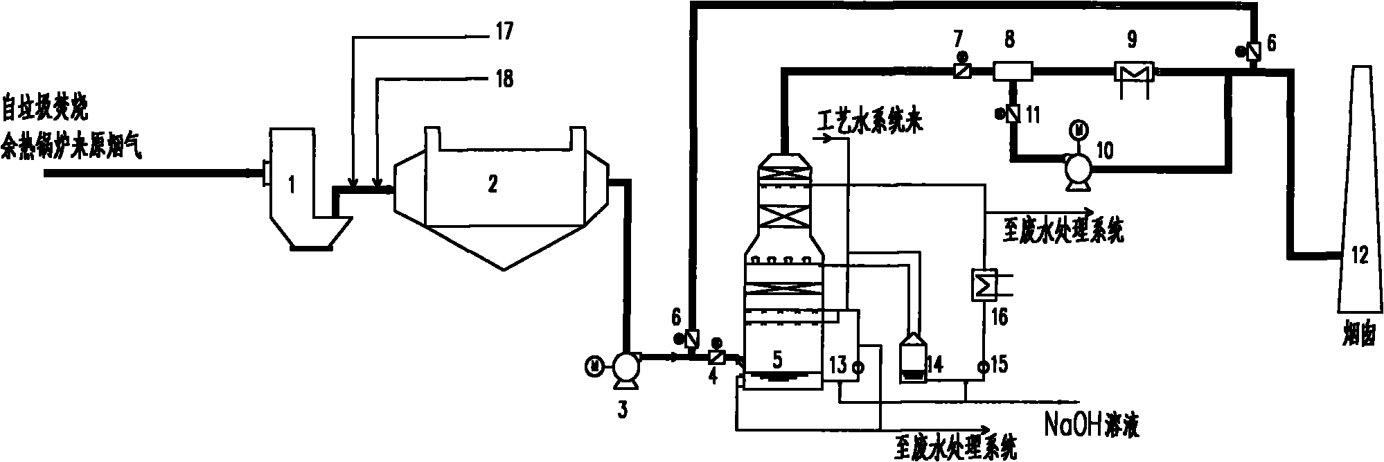
[0026] Such as figure 1 As shown, the process flow of the waste incineration wet flue gas purification process method of the present invention is divided into the following steps:

[0027] (1) Flue gas cooling

[0028] The temperature of the flue gas produced after garbage incineration is relatively high, and a cooling tower 1 is installed between the waste heat boiler and the bag filter 2 to spray water to reduce the temperature of the flue gas. The cooling water and the compressed air pass into the nozzle at the top of the cooling tower 1. The compressed air atomizes the cooling water, and the temperature of the flue gas is reduced from 190°C to about 150°C through the volatilization of moisture. This temperature is suitable for Ca(OH) 2 The temperature at which the adsorption neutralizes the reaction of HCl gas. The cooling effect of this cool...


PUM


Abstract

The invention discloses a flue-gas cleaning method for waste incineration, which comprises a dry process and a wet process. In the dry process, harmful substance in the flue gas is adsorbed by utilizing an adsorbent, and acid gas is neutralized by utilizing an alkaline absorbent, and in the wet process, a wet spray scrubber is utilized to purify the flu gas with higher efficiency. In addition, the invention also discloses a flue-gas cleaning system for waste incineration, which comprises a cooling tower, a bag-type dust collector, a wet washing tower and a glue-gas reheater. Flue gas from an exhaust-heat boiler enters the bag-type dust collector after being cooled by the cooling tower. Activated carbon and slaked lime powder are sprayed into the flue gas before the flue gas enters the bag-type dust collector to carry out preliminary purification on the flue gas; the purified flue gas is introduced to the wet washing tower through a draught fan for further processing; and the purified flue gas is discharged into the atomosphere by a chimney after the two-stage heating. The invention can effectively remove pollutant in flue gas and the quality of the purified flue gas can achieve the EU 2000 effluent standard.

Description

technical field [0001] The invention relates to a flue gas purification method belonging to the field of environmental protection, in particular to a flue gas purification method for garbage incineration; in addition, the invention also relates to a flue gas purification system for garbage incineration. Background technique [0002] Waste incineration is an important method of waste disposal. As an effective process, it has been increasingly adopted by economically developed areas with relatively scarce land resources. Due to the complex composition of garbage, the flue gas produced by incineration of garbage contains a large amount of toxic and harmful substances, which need to be purified and removed to avoid secondary pollution to the environment. [0003] The flue gas purification process is determined according to the composition and concentration of pollutants in the waste gas generated during the waste incineration process and the emission standards that need to be im...

Claims


Application Information

Patent Timeline
Patent Type & Authority Applications(China)
IPC IPC(8): B01D50/00B01D53/02B01D53/83B01D53/78F23J15/00
Inventor 刘东初李建平陈焕莹
Owner 山东三融环保工程有限公司
Why Eureka
Try Eureka