

Construction method of sole plate post-poured strip form bracing system
A technology of a foundation floor and a construction method, which is applied in the treatment of formwork, the treatment of building materials, the preparation of building components on site, etc., can solve the problem of affecting the construction quality, pollution of the cavity of the post-cast belt, and difficulty of the support material of the post-cast belt. Demolition and other problems, to achieve the effect of simple construction, ensure construction quality, simple production and operation process
- Summary
- Abstract
- Description
- Claims
- Application Information
AI Technical Summary
Problems solved by technology
Method used
Image

Examples
Embodiment Construction
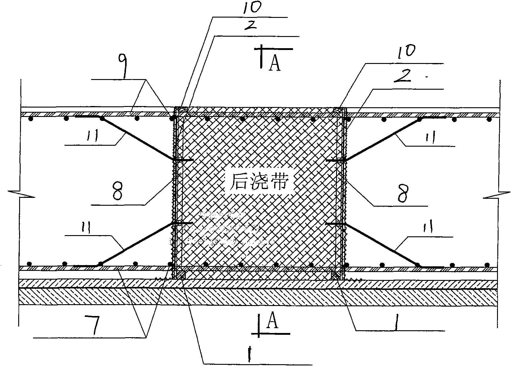
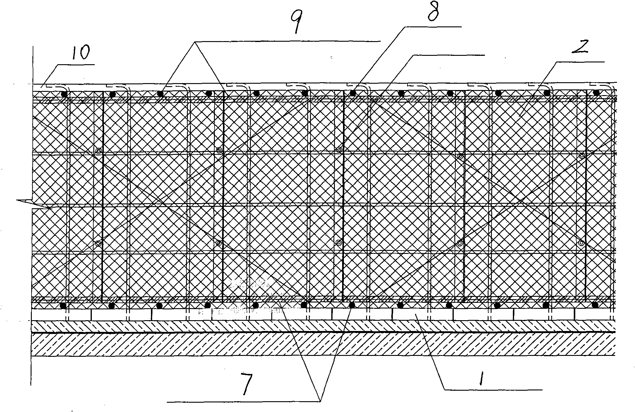
[0025] A construction method of a post-cast belt formwork support system for a foundation base plate, comprising the following steps:
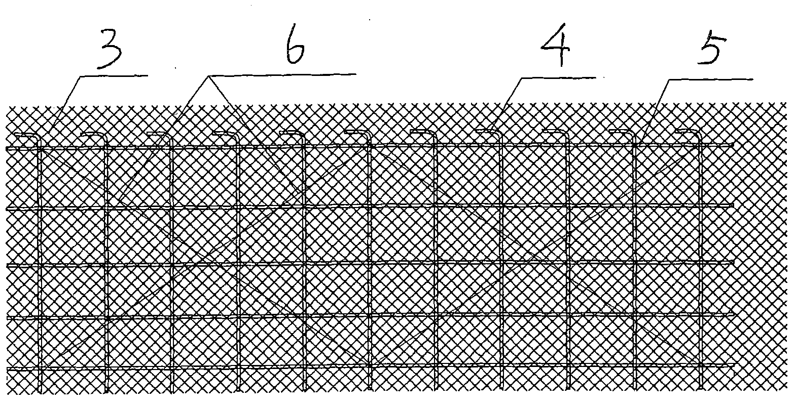
[0026] 1) Prefabricated concrete grout block 1, and made steel mesh mold 2; steel mesh mold includes steel mesh 3, and each steel mesh is rectangular, and the steel mesh is bound with vertical steel bar 4, horizontal steel bar 5 and scissors type lead wire oblique Pull bar 6, the end of the vertical steel wire is provided with a 90-degree hook to facilitate the removal of the vertical steel bar and the horizontal steel bar; 80-120mm steel mesh margins are reserved for the upper and lower sides of the steel mesh mold, which is used to surround the corners of the post-casting belt. It is used for wrapping and retaining grout; 180-220mm of steel mesh margin is reserved on one side of each steel mesh mold, which is to facilitate on-site binding and lap connection between steel mesh molds;
[0027] 2) After pouring and smoothing the foundation floo...
PUM
 Abstract
Description
Claims
Application Information