Supercharge Your Innovation With Domain-Expert AI Agents!

Evaporation equipment

A technology of evaporation equipment and evaporation source, which is applied in the direction of vacuum evaporation plating, ion implantation plating, metal material coating technology, etc., which can solve the problems of poor uniformity of film formation, increased area of ​​glass substrate, and difficult realization Large area and other problems, to achieve the effect of uniform coating on a large area, improve utilization rate, and improve production efficiency

Inactive Publication Date: 2010-09-22
涂爱国
View PDF5 Cites 6 Cited by
  • Summary
  • Abstract
  • Description
  • Claims
  • Application Information

AI Technical Summary

Problems solved by technology

At present, although some companies have obtained authorization, mass-produced OLEDs still use the method of vacuum thermal evaporation. In the case of large-scale mass production and consideration of operating costs, vacuum thermal evaporation also has application limitations, such as film formation. The uniformity of the evaporation will be limited by the area of ​​the evaporation source and the uniformity will be poor. This phenomenon will become more serious as the area of ​​the glass substrate increases.
In addition, there are issues such as the utilization rate of materials, evaporation rate, etc.
Ordinary thermal evaporation source (point source) can only achieve 3.5-generation line due to uniformity, that is, the substrate size is small, and it is difficult to achieve large-area

Method used


Image

  • Evaporation equipment
  • Evaporation equipment
  • Evaporation equipment

Examples


Embodiment Construction

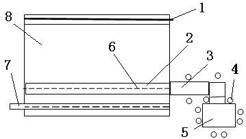
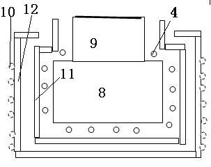
[0025] Specific embodiments of the present invention, such as figure 1 with figure 2 As shown, an evaporation device includes:

[0026] (A) An evaporation source 5, which can heat the source material to vaporize to produce source material vapor;

[0027] (B) A box 8 connected to the evaporation source 5 through a conduit 3, the box 8 has a linear outlet 1, and the linear outlet 1 guides the vapor in the box 8 to flow to the substrate;

[0028] (C) The heating component 4 that prevents material from being deposited on the inner wall of the box 8;

[0029] (D) Two-layer shells 11, 12 and cooling pipes 10 distributed around the box 8 and the evaporation source 5.

[0030] In the above embodiment, the shell can be a layer; inside the box 8 there is a pipe 2 connected to the evaporation source 5, and holes 6 are distributed on the pipe 2 to make the vapor uniformly distributed in the slit direction of the linear outlet 1, where the holes 6 does not point to the direction of the linear ope...


PUM


Abstract

The invention discloses evaporation equipment. The evaporation equipment is characterized by comprising (a) at least one evaporation source, (b) a box, (c) a heating component and (d) an outer shell and cooling pipes, wherein the at least one evaporation source can heat a source material to evaporate the source material so as to produce vapor of the source material; the box is connected with the evaporation source and provided with a linear outlet which leads the vapor in the box to a substrate; the heating component prevents the material from being deposited on the inner walls of the box and a guide pipe; and the cooling pipes are distributed around the box and the evaporation source. The evaporation equipment has the advantage of realizing large-area uniform filming, can easily realize uniform mixing and vapor deposition of two or more materials, speed up the rate of the deposition of the thin film and improve the utilization ratio of the material.

Description

Technical field [0001] The present invention relates to evaporation equipment for evaporation. Background technique [0002] Organic electroluminescent devices (OLEDs) are currently widely used in multi-layered organic films, which serve as electron-hole transport and light-emitting layers. The outside is transparent electrode indium tin oxide (ITO) as the anode, which forms a sandwich structure with another metal cathode to sandwich the organic material between the two electrodes. In the mass production process, indium tin oxide (ITO) is often deposited on the glass substrate by sputtering, and then the surface is treated with oxygen plasma. This method can improve the work function of indium tin oxide (ITO) and make the device operate When holes are more easily injected into the organic layer, the operating voltage can be reduced and the luminous efficiency of the device can be improved. After the anode surface treatment is completed, the organic material can be deposited. S...

Claims


Application Information

Patent Timeline
IPC IPC(8): C23C14/26
Inventor 涂爱国
Owner 涂爱国
Features
  • R&D
  • Intellectual Property
  • Life Sciences
  • Materials
  • Tech Scout
  • Unparalleled Data Quality
  • Higher Quality Content
  • 60% Fewer Hallucinations
Learn More