Tower for flue gas desulfurization in homogeneous air-humidifying method

A desulfurization tower, rheumatism technology, applied in separation methods, chemical instruments and methods, calcium/strontium/barium sulfate, etc., can solve the problem of uneven distribution of gas-liquid two-phase flow velocity, increased pressure drop in the tower, and reduced desulfurization efficiency and other problems, to achieve the effect of reducing operating costs, reducing consumption, and uniform flow field distribution

Inactive Publication Date: 2010-09-29
SHANGHAI UNIVERSITY OF ELECTRIC POWER
View PDF3 Cites 13 Cited by
  • Summary
  • Abstract
  • Description
  • Claims
  • Application Information

AI Technical Summary

Problems solved by technology

[0004] However, for the current traditional desulfurization tower, since the flue gas enters the tower from the side and then turns to flow upward, this causes the uneven

Method used


Image

  • Tower for flue gas desulfurization in homogeneous air-humidifying method
  • Tower for flue gas desulfurization in homogeneous air-humidifying method
  • Tower for flue gas desulfurization in homogeneous air-humidifying method

Examples


Embodiment 1

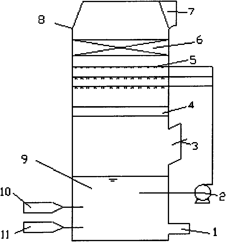
[0036] Such as figure 1 The uniform air distribution flue gas desulfurization tower shown

[0037] A flue gas desulfurization tower device of evenly distributed rheumatic method, comprising a desulfurization tower 8, said desulfurization tower 8 comprising a flue gas inlet 3, a flue gas outlet 7, a desulfurization product slurry outlet 1, a slurry spray area 5, and a demister Zone 6, desulfurizer slurry pool 9, limestone slurry external supply device 10, oxidation air system 11, slurry circulation pump 2 and Venturi diversion tube zone 4;

[0038] The flue gas outlet 7 is opened at the top of the desulfurization tower 8, and the desulfurizer slurry pool 9 is arranged at the bottom of the desulfurization tower 8,

[0039] There is a desulfurization product slurry outlet 1 on the bottom side of the desulfurization agent slurry pool 9;

[0040] Limestone slurry external supply device 10 and oxidation air system 11 are respectively connected with desulfurizer slurry pool 9;

[...

Embodiment 2

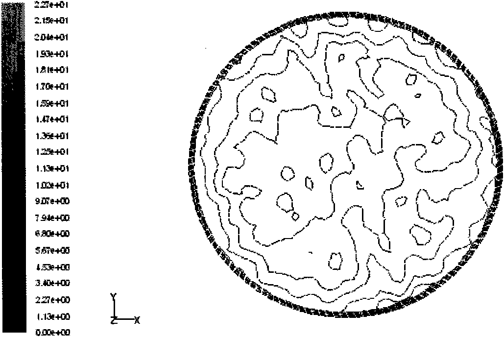
[0046] Use traditional flue gas desulfurization towers with non-uniform air distribution for desulfurization

[0047] Flue gas discharged from the boiler, where SO 2 The concentration is 1500mg / m 3 , after being dedusted by the electrostatic precipitator, the flue gas flow rate is selected to be 6785m through the booster fan 3 / L is sent into the desulfurization tower 8 through the flue gas inlet 3 of the desulfurization tower 8. The flue gas is divided into two paths, respectively forming a clockwise and a counterclockwise vortex to flow upward, and continue to flow upward, passing through the staggered arrangement in the desulfurization In the upper spray area 5 of the tower 8, the limestone slurry in the slurry pool 9 passes through the limestone slurry circulation pump 2 at a flow rate of 67.85m 3 / L is continuously transported to the spray area 5, sprayed out through the nozzle, and contacts with the flue gas countercurrently, thereby completing the desulfurization. Si...

Embodiment 3

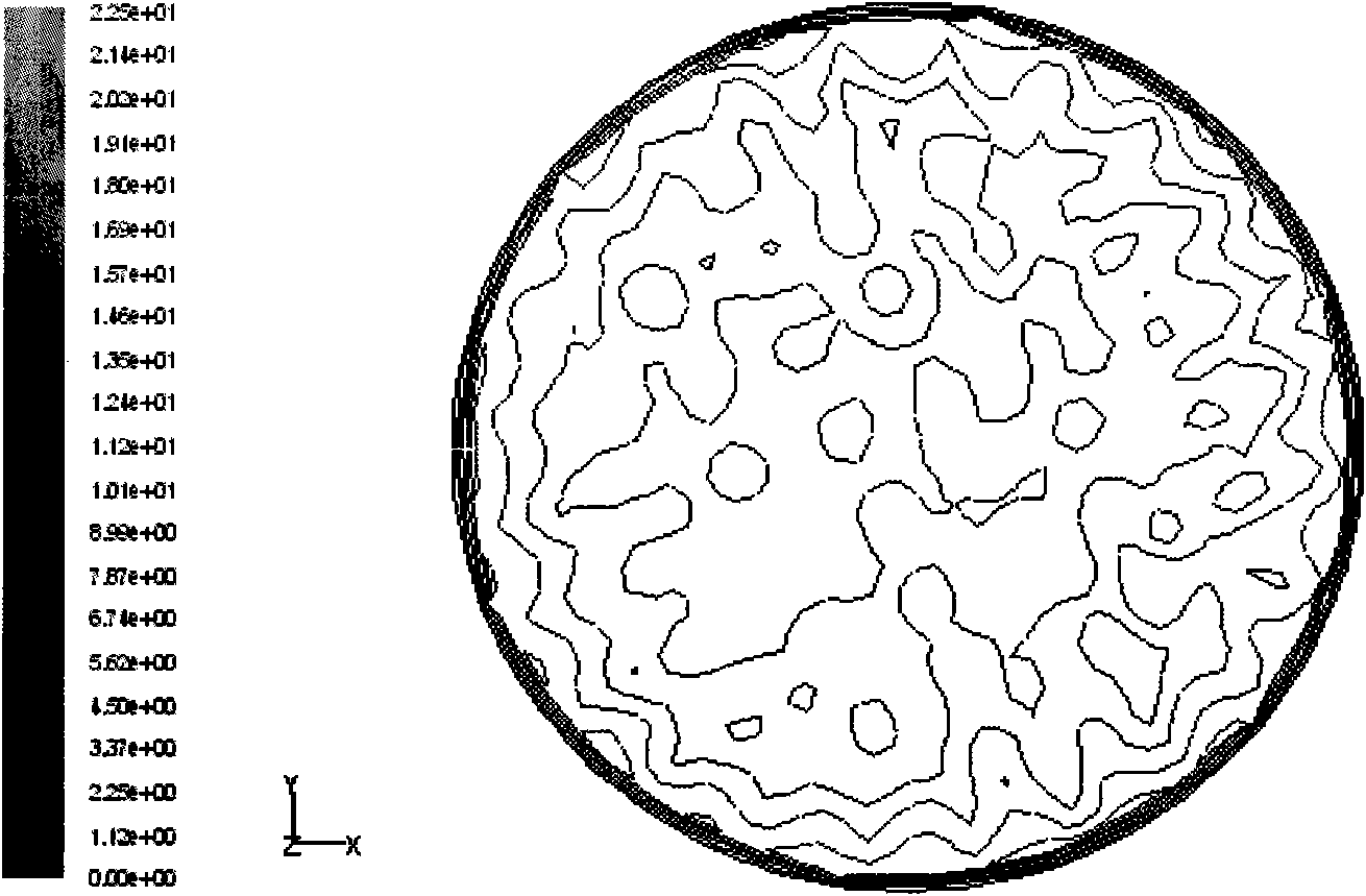
[0050] The flue gas desulfurization tower adopting uniform air distribution of the present invention performs desulfurization

[0051] Flue gas discharged from the boiler, where SO 2 The concentration is 1500mg / m 3 , after being dedusted by the electrostatic precipitator, the flue gas flow rate is selected to be 6785m through the booster fan 3 / L is sent into the desulfurization tower 8 through the flue gas inlet 3 of the desulfurization tower 8. The flue gas is divided into two paths, respectively forming a clockwise and a counterclockwise vortex to flow upward, and is rectified by the Venturi guide tube 4 to form a uniform distribution. The flue gas is turbulent and continues to flow upwards, passing through the spray area 5 staggeredly arranged above the middle of the desulfurization tower 8, and the limestone slurry in the slurry pool 9 passes through the limestone slurry circulation pump 2 at a flow rate of 67.85m 3 / L is continuously transported to the spray area 5, sp...


PUM

PropertyMeasurementUnit
Particle sizeaaaaaaaaaa

Abstract

The invention discloses a tower for flue gas desulfurization in a homogeneous air-humidifying method. In the technical scheme, the top of the desulfurization tower is provided with a flue gas outlet, the bottom thereof is provided with a desulfurizer slurry tank, a flue gas inlet, a venturi draft tube zone, a slurry spray zone and a mist eliminator zone which are inclined downwards are arranged between the desulfurizer slurry tank and the top flue gas outlet in sequence from bottom to top, and the desulfurizer slurry tank is connected with the slurry spray zone through an external slurry circulating pump and is also connected with an external limestone slurry supply device and an oxidation air system. The flue gas forms a uniform upward turbulent flow through the venturi draft tube after flowing into the desulfurization tower, then passes through the slurry spray zone arranged in a staggered way so that SO2 in the flue gas can be transformed into CaSO3, and is finally oxidized into gypsum after being dropped into the slurry tank below the tower along with absorption slurry droplets. Compared with the conventional desulfurization tower, the gas-liquid mass transfer efficiency can reach 20-30 percent, the desulfurization efficiency is up to more than 97 percent, the liquid-gas ratio can be reduced by 3-5L/m2, the structure is simple, and the cost is low.

Description

technical field [0001] The invention relates to a purification treatment technology for flue gas discharged from coal-fired power plant boilers, in particular to a uniformly distributed rheumatic desulfurization tower device. Background technique [0002] In my country's primary energy composition, coal occupies an absolute dominant position. Coal-based thermal power generation produces a large amount of pollutants when coal is burned. It is currently the largest source of air pollution in my country, and its harmfulness has become a consensus. SO from coal burning 2 And acid rain pollution is not only the main problem of air pollution in China, but also an important environmental factor restricting the coordinated and stable economic development. In general, SO 2 Total emissions and SO in flue gas 2 The concentration increase rate is related to the amount of coal burned and the sulfur content of the coal. As a large coal-burning household, the power industry consumes m...

Claims


Application Information

Patent Timeline
IPC IPC(8): B01D53/80B01D53/50C01F11/46
Inventor 郭瑞堂潘卫国冷雪峰张晓波徐宏建
Owner SHANGHAI UNIVERSITY OF ELECTRIC POWER
Why Eureka
Try Eureka