Eureka AIR delivers breakthrough ideas for toughest innovation challenges, trusted by R&D personnel around the world.

Hydraulic waste drilling machine

A hydraulic and drilling machine technology, used in rotary drilling rigs, impact drilling, rotary drilling and other directions, can solve the problem that the drilling machine relies heavily on labor, the guarantee rate of hole-forming quality is low, and the hole-forming efficiency is reduced. problems, to achieve the effect of improving loading and unloading efficiency and hole forming efficiency, reducing hole forming time, and solving hole forming difficulties

Active Publication Date: 2012-08-08
JIANGSU ZHONGYI ECOLOGICAL SOIL INST
View PDF0 Cites 0 Cited by
  • Summary
  • Abstract
  • Description
  • Claims
  • Application Information

AI Technical Summary

Problems solved by technology

[0005] At present, relevant equipment has been developed for landfills in China. However, due to the small hole diameter and low stability, repeated drilling is common, resulting in very low hole formation efficiency. Moreover, a considerable part of the drilling rigs rely on manual drilling. If the degree is too high, it is also an important factor that drastically reduces the pore-forming efficiency.
In foreign countries, landfill gas resource utilization facilities and machinery have been developed earlier, but at present, the mechanical cost of drilling holes for landfill bodies is high, the quality assurance rate of holes is low, and the drilling rate is not high, which is difficult to meet the promotion of landfill in my country. Requirements for promotion of gas energy conversion

Method used


Image

  • Hydraulic waste drilling machine
  • Hydraulic waste drilling machine
  • Hydraulic waste drilling machine

Examples


Embodiment Construction

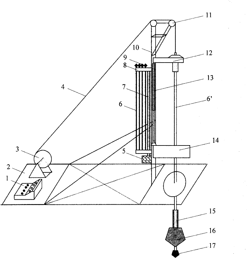
[0012] Below in conjunction with accompanying drawing, the hydraulic type garbage drilling machine of the present invention of the present invention is described in further detail:

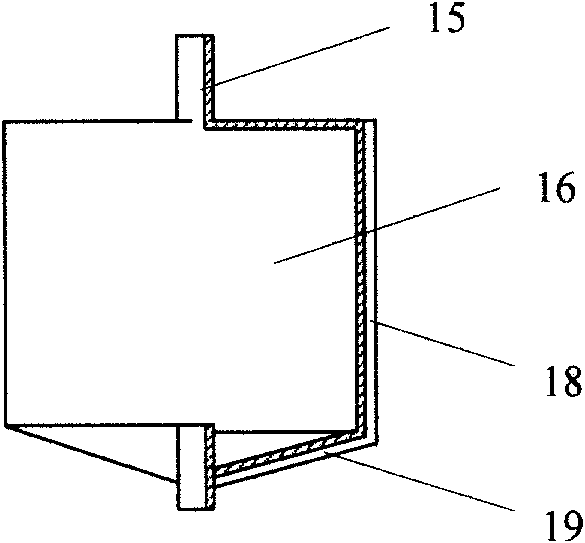
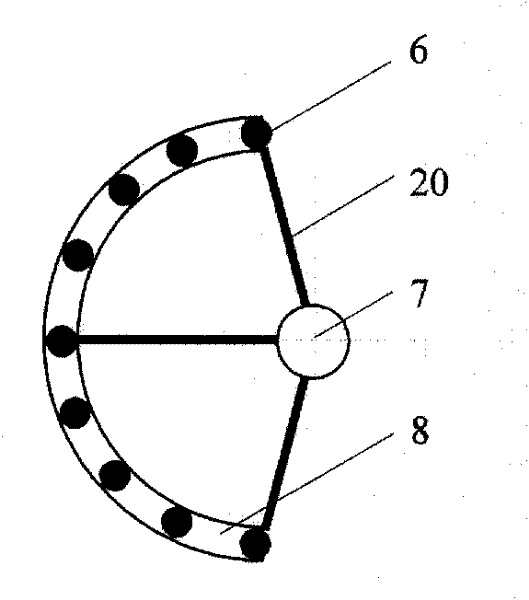
[0013] The hydraulic drilling machine consists of a control cabinet 1, a drill frame 2, a winch 3, a drill pipe slot 8, an overhead wheel 11, a chuck 12, a hydraulic rod 13, a drill pipe 6, a floating rail turntable 14, a drill collar 15, and a combination The drill bit is composed of a control cabinet 1, a hoist 3 and a vertical support 10 fixedly installed on the drill frame 2, and the steel cable 4 on the hoist 3 is connected to the chuck 12 through the sky wheel 11. The control cabinet 1 controls the hydraulic rod 13 of the hydraulic drilling, the winch 3 , the floating rail type turntable 14 and the torsional power device 5 . The hydraulic rod 13 is positioned at one side of the vertical support 10, its lower end is connected to the floating rail type turntable 14 and the upper end is connect...


PUM


Abstract

The invention discloses a hydraulic waste drilling machine, which adopts a combined drill bit with a leading drill bit and rotating bucket drill drilling structure, realizes the functions of the preliminary hole formation of the leading drill bit and the reaming, strengthening and drilling of the rotating bucket drill, and ensures the stability of hole drilling and hole forming rate during gradual drilling. The assembly and disassembly structure of a sliding multi-drill pipe improves the handling efficiency of the drill pipe, and is combined with the leading drill bit and rotating bucket drill drilling structure to shorten the hole forming time and improve the hole forming efficiency of the drilling machine. A hydraulic system is used for loading drilling force so as to greatly reduce thehole forming time. The drilling machine can quickly form holes and does not need strengthening, solves the difficulties of difficult hole formation, poor stability and low drilling efficiency of landfill, and indirectly improves the construction efficiency of a drilling and gas collecting system of landfill sites, and reduces the operating cost.

Description

technical field [0001] The invention discloses a hydraulic garbage drilling machine, which belongs to the category of engineering machinery. Background technique [0002] With the gradual implementation of national policies on environmental protection, low-carbon emission reduction and resource utilization, the resource utilization of landfill gas generated during the large-scale construction of domestic waste landfills has become an urgent problem in the field of national energy and environment. major environmental issues. The efficient collection of landfill gas is of great practical significance to promote the resource utilization of landfill gas and improve the operation and management of landfill sites. [0003] At present, landfill gas collection mainly adopts two methods: vertical collection and horizontal collection. Most domestic waste landfills adopt the vertical collection method, mainly for closed landfills or capped landfill units, using the landfill gas gabio...

Claims


Application Information

Patent Timeline
Patent Type & Authority Patents(China)
IPC IPC(8): E21B3/00E21B10/43E21B10/26E21B19/18
Inventor 薛强李先旺胡竹云席本强
Owner JIANGSU ZHONGYI ECOLOGICAL SOIL INST
Why Eureka
Eureka Blog
Learn More