Supercharge Your Innovation With Domain-Expert AI Agents!

Permanent magnet engine

A permanent magnet and engine technology, applied in electromechanical devices, electrical components, etc., can solve the problems of inability to use on the ground, heavy electric energy storage equipment, and high battery manufacturing costs, and achieve the effects of easy starting, low power, and high torque.

Inactive Publication Date: 2010-10-06
尚世群
View PDF0 Cites 0 Cited by
  • Summary
  • Abstract
  • Description
  • Claims
  • Application Information

AI Technical Summary

Problems solved by technology

In the above various power equipment, the pneumatic motor needs to use the pressure energy of compressed air or steam pressure energy, but the high-pressure air needs to be converted by electricity, and the steam needs to be converted by heat energy; the electric motor is converted into kinetic energy by using electricity. For vehicles, the electric energy storage equipment is heavy, the use time is short, and the manufacturing cost of the battery is high; the engine is also called an internal combustion engine, which uses chemical energy to convert into kinetic energy, but the tail gas emitted by the internal combustion engine pollutes the environment very high; hydrogen energy engines It uses chemical energy to convert into kinetic energy, but the production of hydrogen requires a large amount of electric energy; nuclear energy engines use nuclear fusion or nuclear fission to generate kinetic energy, which is difficult to manufacture and expensive, and the radiation of nuclear fuel has serious damage to the human body; plasma The engine uses electric energy, but because of its small power, it can only operate in space and cannot be used on the ground

Method used


Image

  • Permanent magnet engine
  • Permanent magnet engine
  • Permanent magnet engine

Examples


Embodiment Construction

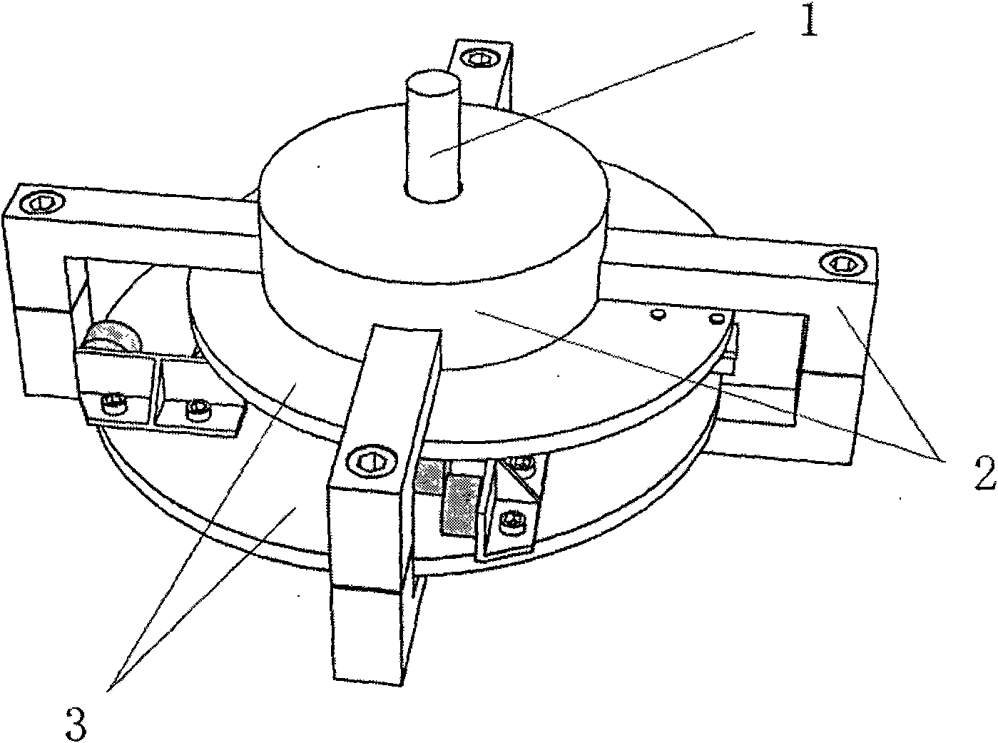
[0025] Such as figure 1 Shown is a schematic diagram of the appearance of the engine, from which it can be understood that the present invention is composed of a rotor and a stator. Its structure is that the output shaft (1) is inserted into the casing (2), so that it can rotate without eccentricity in the casing, and the rotor (3) of the present invention is also arranged in the casing, and the rotor is fixed in the stator. At the same time, non-eccentric rotation is also performed.

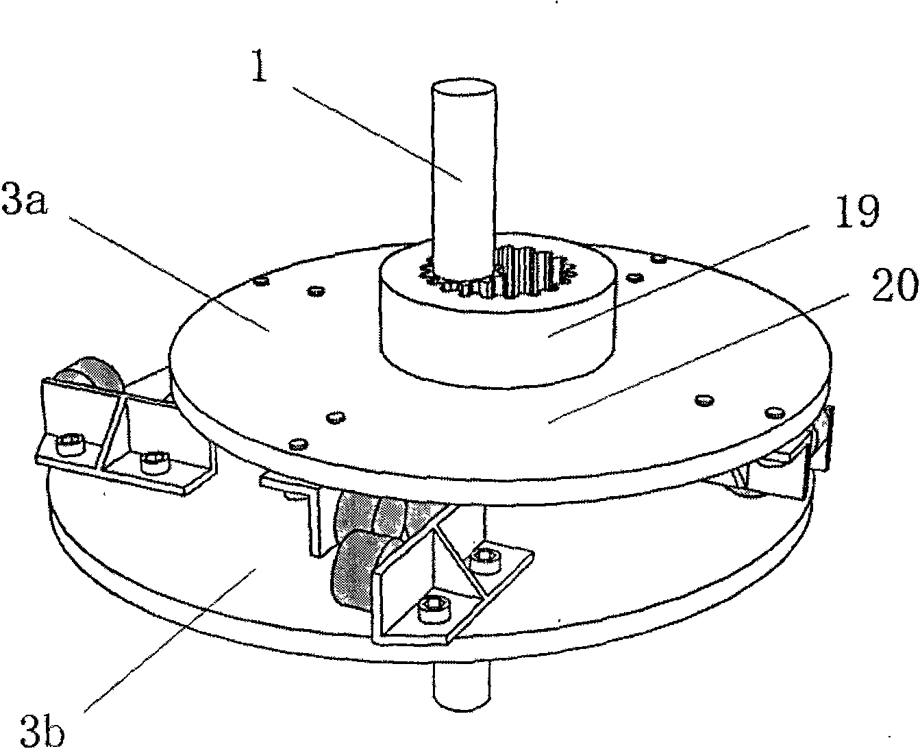
[0026] Such as figure 2 Shown is a schematic diagram of the rotor assembly of the present invention, the rotor assembly of the present invention is formed by inserting the output shaft (1) into the upper rotor (3a) and the lower rotor (3b). The structures of the upper and lower rotors (3a) (3b) are basically the same, but different in size. All of them are composed of rotor journal (19) and rotor disc (20). Bearings are sheathed on the rotor journal (19), so that one side of the rotor disk ...


PUM


Abstract

The invention discloses a permanent magnet engine. An upper circular disc and a lower circular disc with different sizes are arranged non-coaxially and oppositely, and one side of each circular disc is provided with a bearing for making the circular disc fixed in a shell and rotated without eccentric; internal gears are arranged in the centers of the two circular discs; an output shaft with a sun gear is inserted into an intersection between the internal gears of the two circular discs, and the two circular discs are connected to realize that the two circular discs are rotated at the same angular speed and in the same direction; inner sides of the two circular discs are provided with a plurality of permanent magnets with corresponding quantity; and when the plurality of permanent magnets are on the same plane, an interaction force which is generated between magnetic poles drives a rotor to rotate to form the continuous rotation permanent magnet engine.

Description

a technical field [0001] The invention relates to a permanent magnet motor, in particular to a motor that uses permanent magnet energy of permanent magnets and continuously outputs kinetic energy through mechanical means without other energy input. Two background technology [0002] In today's modern society, all walks of life need to use power equipment, such as transportation, manufacturing, and currently among the existing power equipment, pneumatic motors or electric motors or engines are widely used power conversion equipment. In addition, in today's global energy-saving environment, new-generation energy engines will gradually be widely used, such as hydrogen energy engines, nuclear energy engines, and plasma engines. In the above various power equipment, the pneumatic motor needs to use the pressure energy of compressed air or steam pressure energy, but the high-pressure air needs to be converted by electricity, and the steam needs to be converted by heat energy; the ...

Claims


Application Information

Patent Timeline
IPC IPC(8): H02K53/00
Inventor 尚世群
Owner 尚世群
Features
  • R&D
  • Intellectual Property
  • Life Sciences
  • Materials
  • Tech Scout
  • Unparalleled Data Quality
  • Higher Quality Content
  • 60% Fewer Hallucinations
Learn More