Renewable energy fluid pump to fluid-based energy generation

A fluid and energy technology, applied in the field of renewable energy fluid pumps used to generate energy based on fluids, can solve problems such as expensive, difficult to access and repair, maintenance failure and failure, etc., to reduce greenhouse gas production, improve productivity and Reliability, the effect of reducing maintenance costs

Inactive Publication Date: 2010-10-06
DEHLSEN ASSOC LLC
View PDF1 Cites 8 Cited by
  • Summary
  • Abstract
  • Description
  • Claims
  • Application Information

AI Technical Summary

Problems solved by technology

This electrical equipment, with its many connections and electrical controls, is expensive, high maintenance and prone to failure and failure due to exposure to harsh environments, and difficult to access and repair in a marine environment over a wide range of sea conditions

Method used


Image

  • Renewable energy fluid pump to fluid-based energy generation
  • Renewable energy fluid pump to fluid-based energy generation
  • Renewable energy fluid pump to fluid-based energy generation

Examples


Embodiment Construction

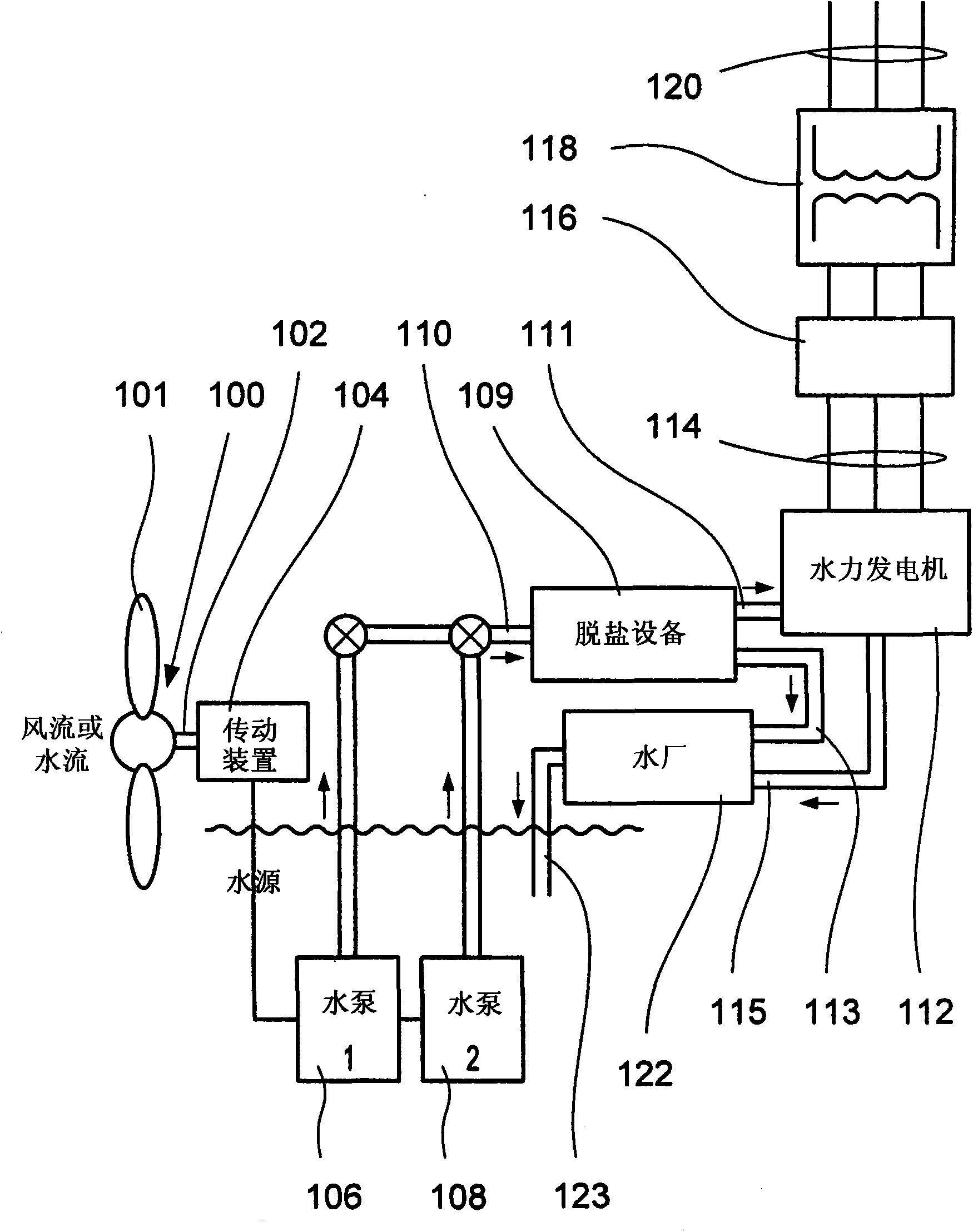
[0049] figure 1 An embodiment of a system for converting kinetic energy of a first fluid is illustrated. figure 1 The system includes a fluid driven turbine 100, 102, 104 driving two fluid pumps 106, 108 for pressurizing the water. A fluid pump is connected to transfer line 110 and provides pressurized water fluid to the transfer line, where transfer line 110 is connected to hydroelectric generator 112, a device for harnessing the energy of the pressurized water as power.

[0050] In other words, figure 1 Illustrated is a system in which the energy harnessed by the fluid-driven turbines 100, 102, 104 is transferred by a pressurized fluid flow to an onshore station where the pressurized fluid flow drives the hydraulics 112. The device 112 can be any energy recovery device such as a hydroelectric system to generate electricity, a desalination plant 109 to filter out fresh water (fresh water stream 113) for drinking or irrigation, use of cold water storage in a district (air co...


PUM


Abstract

A wind or water turbine mounted atop a support tower or tethered underwater drives a hydro-pumping system. The turbine converts wind or water energy into a driving torque applied to the hydro-pump. The hydro-pump forces water through a pipe transmission system to an onshore facility. On shore, the resultant pressurized fluid-flow propels a hydroelectric generating system to produce electricity or may first be used in a Reverse Osmosis desalinization process and the byproduct in part used to propel a hydroelectric generating system to produce electricity. The cold-water discharge from the hydroelectric generating system and / or from the desalinization process is used for onshore district or power plant cooling purposes.

Description

technical field [0001] The present invention relates to fluid-driven turbines and methods for operating such fluid-driven turbines, and more particularly to apparatus and methods for converting the kinetic energy of a fluid driving the turbine. Background technique [0002] Renewable energy generation technologies for offshore applications are largely based on wind turbines and more recently tidal, wave and ocean current turbines, all of which currently or plan to drive generators and transmit power to shore via high-voltage submarine cables. This electrical equipment, with its many connections and electrical controls, is expensive, highly maintenance demanding and prone to malfunction and failure due to exposure to harsh environments, and difficult to access and service over a wide range of sea conditions in a marine environment. Some of the problems described above also occur in the case of erecting high voltage cables. [0003] The close proximity of multiple, high press...

Claims


Application Information

Patent Timeline
Patent Type & Authority Applications(China)
IPC IPC(8): F03D9/00
CPCF03B13/00F05B2240/95F05B2210/16F05B2240/97F05B2220/62Y02P80/10
Inventor 詹姆斯·G·P·德尔森克里斯托弗·J·格列科威廉姆·佩茨科
Owner DEHLSEN ASSOC LLC
Why Eureka
Try Eureka