
Electrochemical biological combined denitrification reactor

A technology of electrochemical biology and reactor, which is applied in chemical instruments and methods, sustainable biological treatment, biological water/sewage treatment, etc. It can solve the problems of uncontrollable denitrification intensity, achieve small footprint and avoid sludge Expansive, compact and simple effect

Inactive Publication Date: 2010-10-13
ZHEJIANG GONGSHANG UNIVERSITY
View PDF7 Cites 31 Cited by
  • Summary
  • Abstract
  • Description
  • Claims
  • Application Information

AI Technical Summary

Problems solved by technology

Although the device can carry out nitrification and denitrification synchronously according to the difference of DO on the inner and outer surfaces of microbial flocs, the denitrification reaction of this reaction uses organic matter as the reaction substrate, so it is still impossible to control the denitrification intensity.

Method used


Image

  • Electrochemical biological combined denitrification reactor
  • Electrochemical biological combined denitrification reactor
  • Electrochemical biological combined denitrification reactor

Examples


Embodiment 1

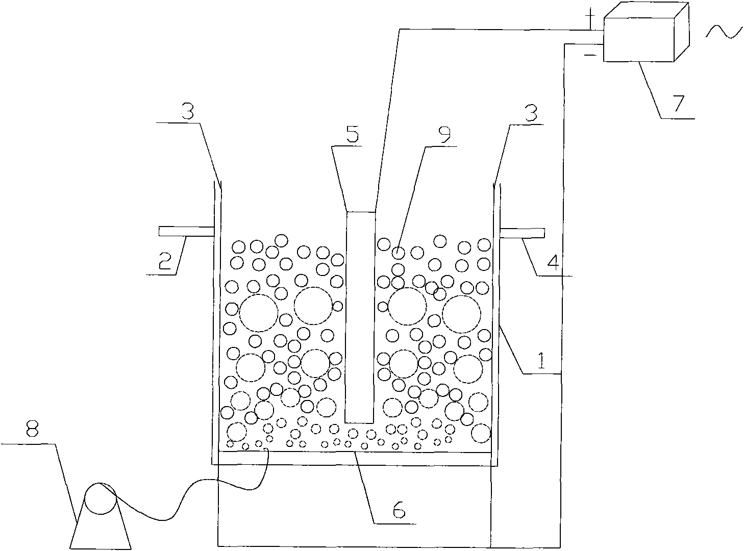
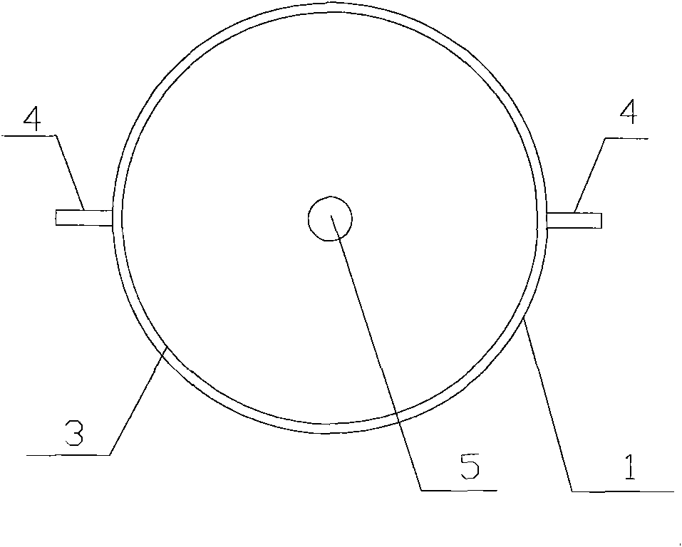
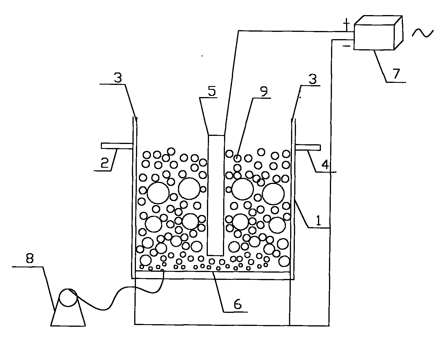
[0014] An electrochemical biological combined denitrification reactor, such as figure 1 , 2 As shown, it includes a cell body 1, an electrode, a modified activated carbon particle electrode 9, an aeration device 8 and a steady current transformer 7. The two ends of the cell body 1 are respectively provided with a water inlet 2 and a water outlet 4; the electrodes include an anode 5 and a cathode 3, the anode 5 is arranged in the center of the cell body 1, and the cathode 3 surrounds the anode 5 and is arranged near the cell wall. The material used for the anode 5 is a titanium plate, and the material used for the cathode 3 is graphite; the anode 5 and the cathode 3 are respectively connected to the positive and negative poles of the steady current transformer 7; the spherical modified activated carbon particle electrode 9 is filled between the anode 5 and the cathode 3; The aeration device includes a microporous aerator 6 arranged at the bottom of the pool body 1 and an air p...

Embodiment 2

[0017] The structure of the reactor is the same as in Example 1, the anode 5 is made of titanium-based lead dioxide-plated material, and the cathode 3 is made of stainless steel. Processing flow is the same as embodiment 1.

[0018] Using a complex three-dimensional electrode-biofilm reactor with a titanium-based lead dioxide-plated material as the anode and a stainless steel cathode as the direct treatment of COD to 45mg / L, NH 3 -N=30mg / L, TN is 40mg / L simulated wastewater, under the conditions of T=28℃, DO=1.2mg / L, HRT=8h, I=25mA, the effluent COD is 30mg / L, TN=3.2mg / L, NH 3 - N = 1.9 mg / L.

Embodiment 3

[0020] The structure of the reactor is the same as in Example 1, the anode 5 is made of titanium-based ruthenium dioxide plated plate material, and the cathode 3 is made of graphite material. Processing flow is the same as embodiment 1.

[0021] Using a complex three-dimensional electrode-biofilm reactor with a titanium-based ruthenium dioxide-coated material as the anode and a graphite material as the cathode, the COD is 45mg / L and NH is directly processed. 3 - Simulated wastewater with N=30mg / L and TN of 40mg / L was carried out under the same conditions as Case 2: T=28°C, DO=1.2mg / L, HRT=8h, I=25mA, and the effluent COD was 26mg / L, TN=1.1mg / L, NH 3 - N = 0.82 mg / L.


PUM

PropertyMeasurementUnit
electric potential / voltageaaaaaaaaaa
particle diameteraaaaaaaaaa

Abstract

The invention discloses an electrochemical biological combined denitrification reactor, which comprises a tank body, an electrode plate, a particle electrode, an aerating apparatus and a constant current transformer. Both ends of the tank body are respectively provided with a water inlet and a water outlet. The electrode plate comprises an anode arranged on the center part of the tank body and a cathode which surrounds the anode to be arranged at the position close to the tank wall; the anode and the cathode are respectively connected with an anode and a cathode of the constant current transformer; the particle electrode is filled between the anode and the cathode; and the aerating apparatus comprises a fine bubble aerator arranged on the bottom of the tank body and an air pump connected with the fine bubble aerator. The device of the invention has compact and simple structure, small occupied area, high current utilization rate and rapid biofilm formation of microbe, can simultaneously remove various pollutants, such as organic matter, ammonia nitrogen and the like, has high denitrification efficiency and low energy consumption, is easy to regulate and control and is a multiple three-dimensional electrode biomembrane sewage treatment device integrating biology with an electric microfield into whole body.

Description

technical field [0001] The invention relates to the field of sewage denitrification treatment reactors, in particular to an electrochemical-biological combined denitrification reactor that adopts a complex three-dimensional electrode biofilm method to strengthen micro-electrolysis denitrification. Background technique [0002] At present, the traditional biological nitrogen removal process arranges nitrification and denitrification as two independent stages in different reactors (in space) or uses intermittent aerobic and anaerobic conditions (in time) to achieve nitrogen removal. Therefore, the denitrification system is often complicated, the energy consumption is large, and the operation and management are inconvenient. However, in recent years, people have often found total nitrogen loss in many aerobic nitrification ponds in actual operation. In addition to partial nitrogen assimilation into microbial cells, a large part of it may be through simultaneous nitrification an...

Claims


Application Information

Patent Timeline
Patent Type & Authority Applications(China)
IPC IPC(8): C02F3/34C02F3/12
CPCY02W10/10
Inventor 冯华军冯小晏钱钰洁郭梦婷
Owner ZHEJIANG GONGSHANG UNIVERSITY
Learn More