Multifocal holographic differential confocal super-large curvature radius measuring method and device

A differential confocal and radius measurement technology, which is applied in the direction of measuring devices, optical devices, instruments, etc., to achieve the effects of reducing system errors, high stability, and small moving distances

Inactive Publication Date: 2010-10-13
BEIJING INSTITUTE OF TECHNOLOGYGY
View PDF5 Cites 26 Cited by
  • Summary
  • Abstract
  • Description
  • Claims
  • Application Information

AI Technical Summary

Problems solved by technology

[0007] The purpose of the present invention is to solve the problem of high-precision measurement of super-large radius of curvature, and propose a method and device for measuring super-large radius of curvature with multi-focus holographic differential confocal

Method used


Image

  • Multifocal holographic differential confocal super-large curvature radius measuring method and device
  • Multifocal holographic differential confocal super-large curvature radius measuring method and device
  • Multifocal holographic differential confocal super-large curvature radius measuring method and device

Examples


Embodiment 1

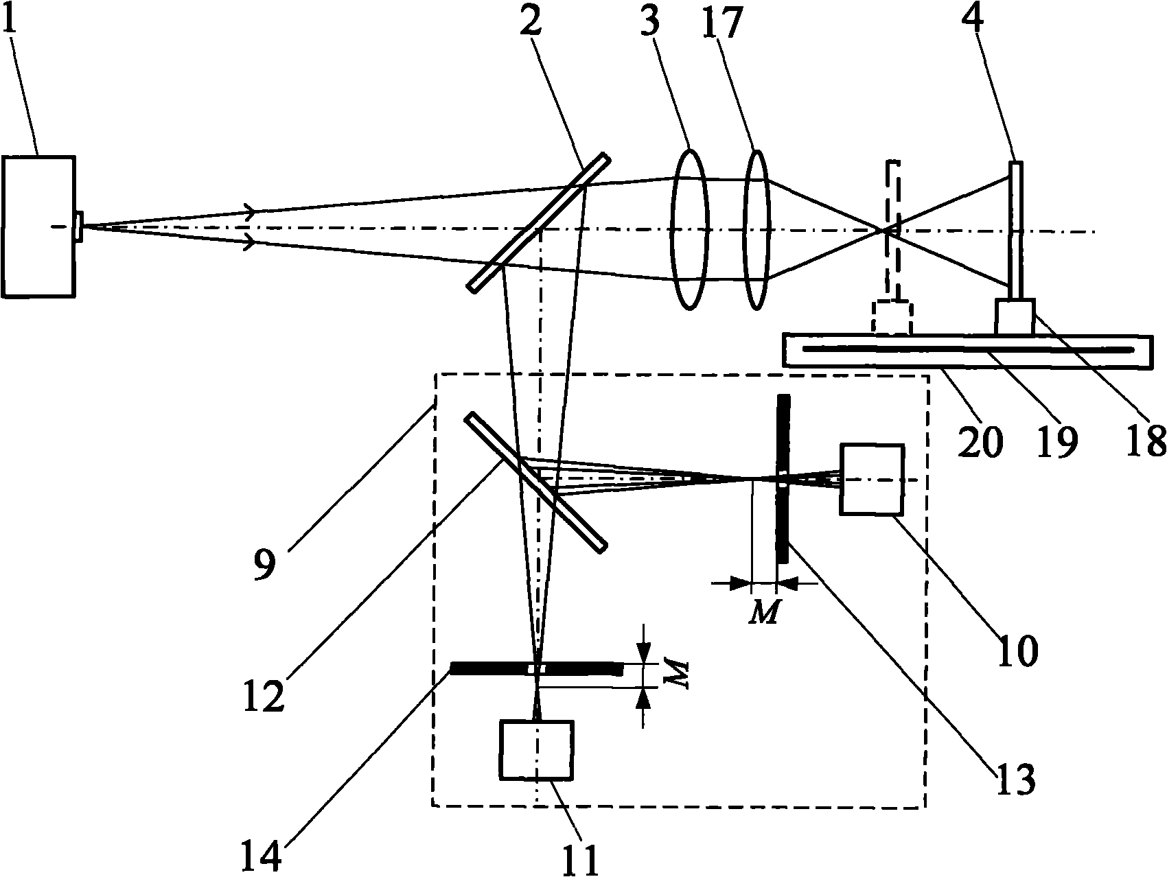
[0047] In this embodiment, a convex lens is adopted as the measured object 7, such as Figure 5 As shown, the multi-focus holographic differential confocal ultra-large radius of curvature measurement device includes a point light source 1, which is placed in turn in the first beam splitter 2, collimator lens 3, multi-focus holographic lens 4 and the measured The component 7 also includes a differential confocal system 9 placed in the reflection direction of the first beam splitter 2;

[0048] The device also includes an adjustment frame 18, a length measuring system 19, a moving guide rail 20, a main control computer 22 and an electromechanical control device 21; The length measurement system 19 is installed on the moving guide rail 20, the main control computer 22 obtains the differential confocal response signal through the first light intensity sensor 10 and the second light intensity sensor 11, and the main control computer 22 controls the electromechanical control device ...

Embodiment 2

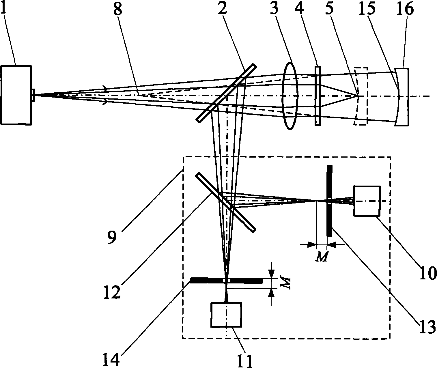
[0062] In the present embodiment, a concave lens is adopted as the measured object 16, such as figure 2 As shown, the difference from Embodiment 1 is that the measured surface 15 of the measured object 16 has a negative radius of curvature, and the -1st order diffracted light in the telephoto region of the multi-focus holographic lens 4 is used to generate divergent spherical waves during measurement, and the detected The confocal position of the measured surface 6 of the test piece 7 is obtained by the first-order diffracted light in the short-focus area of ​​the multi-focal holographic lens 4. The cat’s eye position of the tested surface 6 of the test piece 7 is obtained; The converging point 5 of the beam locates the apex of the measured surface 15 , and the spherical center of the measured surface 15 is positioned by the converging point 8 of the long-focus measuring beam of the multi-focus holographic lens. All the other measuring methods and devices are the same as in E...

Embodiment 3

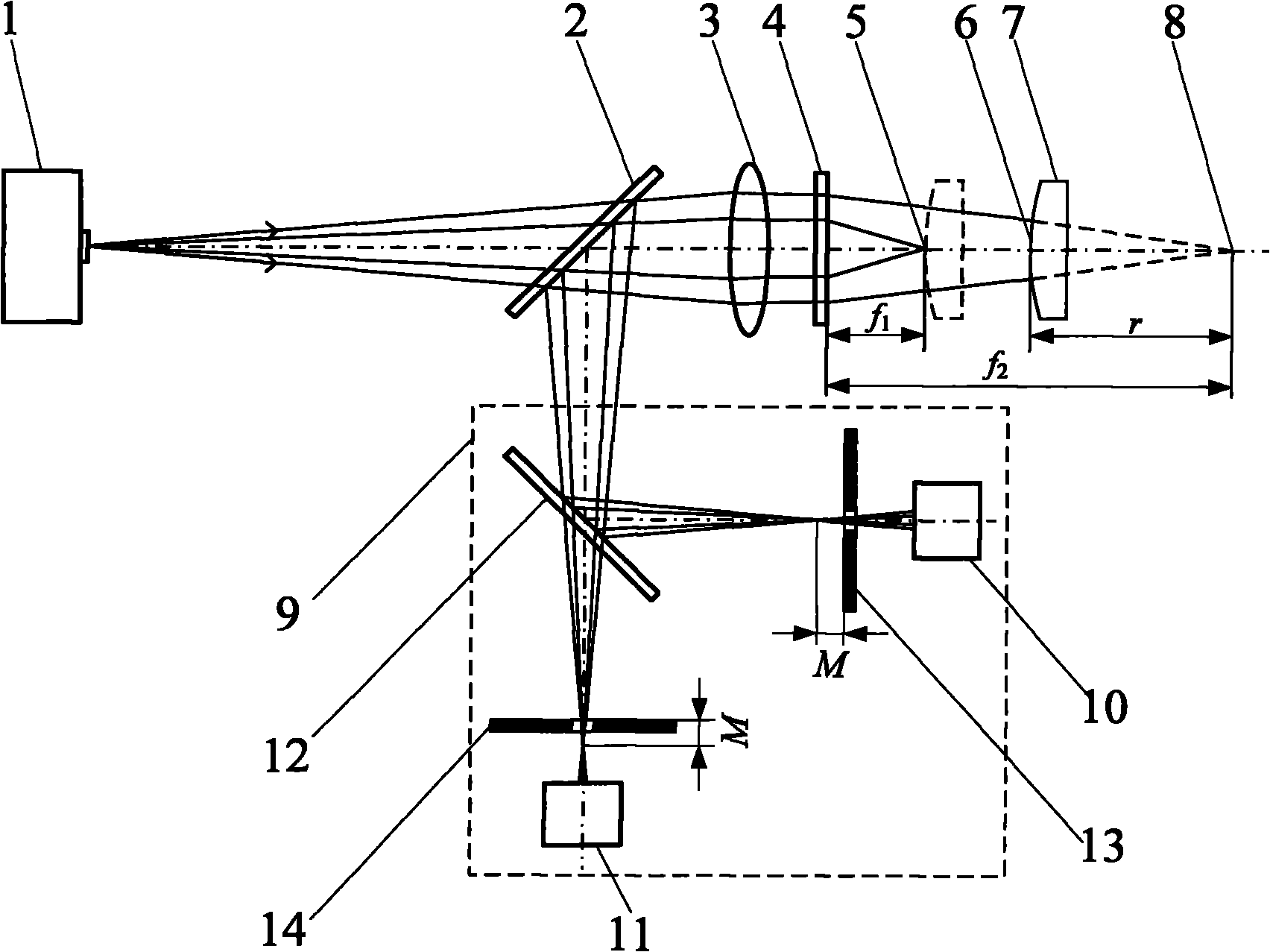
[0064] Example 1 Figure 8 The differential confocal system in 9 is replaced by Image 6 The differential confocal system 9 can constitute the embodiment 2. The difference from Embodiment 1 is that after the light enters the differential confocal system 9, the second beam splitter 12 divides the light into two paths, the reflected light illuminates the first light intensity sensor 10 located behind the focus, and the transmitted light illuminates the first light intensity sensor 10 located before the focus The second light intensity sensor 11. All the other measuring methods and devices are the same as in Example 1.


PUM


Abstract

The invention relates to multifocal holographic differential confocal super-large curvature radius measuring method and device, belonging to the technical field of optical precision measurement. The method comprises the following steps of: firstly, calibrating the long-focus value of a multifocal holographic lens by utilizing a differential confocal system so as to reduce the system error of measurement; realizing non-contact high-precision positioning at the cat eye position and the cofocal position of a measured piece by utilizing a differential confocal fixed-focus principle; and subsequently, realizing the high-precision measurement of a super-large curvature radius by utilizing a geometrical optics principle. The device comprises a point light source, a first spectroscope, a collimator objective, the multifocal holographic lens, the differential confocal system, an adjusting frame, a length measuring system and a moving track. The invention integrates the differential confocal high-precision fixed-focus principle and a multifocal holographic lens compression optical path principle for the first time, has the advantages of small displacement distance of the measured piece, high measurement precision, high measurement speed, strong ambient interference resistance, no damage to the measured surface and the like and can be used for the high-precision non-contact measurement of the super-large curvature radius.

Description

technical field [0001] The invention belongs to the technical field of optical precision measurement and can be used for high-precision measurement of super large curvature radius. Background technique [0002] Large optical components are widely used in large optical systems such as space optical systems, high-energy lasers, and laser nuclear fusion. However, the measurement of the radius of curvature of large optical components has always been one of the difficult problems in the field of optics due to its low precision of fixed-focus aiming, long measurement path and susceptibility to interference from environmental factors. It is a technical bottleneck to be solved urgently in the development of large-scale optical systems such as nuclear fusion. This technical feature will be particularly urgently reflected in major national special projects and major national projects such as space optical instruments, high-energy laser weapons, and laser nuclear fusion projects. [...

Claims


Application Information

Patent Timeline
Patent Type & Authority Applications(China)
IPC IPC(8): G01B11/255
Inventor 赵维谦孙若端史立波邱丽荣
Owner BEIJING INSTITUTE OF TECHNOLOGYGY
Why Eureka
Try Eureka