Vacuum pressure swing adsorption system

A vacuum pressure swing adsorption and vacuum technology, which is applied to the separation of dispersed particles, chemical instruments and methods, separation methods, etc., can solve the problems of shortening the adsorption time, increasing the amount of compressed air, and prolonging the vacuum desorption time, so as to shorten the adsorption time, The effect of reducing the pumping speed of the vacuum pump and prolonging the vacuum desorption time

Active Publication Date: 2012-10-24
BEIJING PEKING UNIV PIONEER TECH
View PDF4 Cites 0 Cited by
  • Summary
  • Abstract
  • Description
  • Claims
  • Application Information

AI Technical Summary

Problems solved by technology

[0006] 1. Since there are only two adsorbers, limited by the size of the adsorber structure, the maximum oxygen production scale is relatively small, only 5000-6000M 3 / h; and if you want to expand the scale of oxygen production to 10000M 3 / h or more, using two or more sets of two-bed VPSA systems in parallel will definitely increase the cost;
[0007] 2. In the existing two-bed VPSA process, the blower supplies air to the adsorber discontinuously. In each cycle, the blower exhausts to the atmosphere twice, each time lasting 2-4 seconds
However, in the existing two-bed and three-bed VPSA processes, the adsorption time is equal to or greater than the vacuum desorption time. If the adsorption time is shortened and the vacuum desorption time is prolonged, the amount of compressed air entering the adsorber per unit time will increase. In addition to increasing the exhaust volume of the blower In addition, the superficial velocity of the compressed air in the adsorber increases
The existing two-bed or three-bed VPSA process has only one vacuum pump to evacuate one adsorber, and the cycle period is fixed, which cannot shorten the adsorption time and prolong the vacuum desorption time, and the required vacuum pump pumping speed is still relatively large

Method used


Image

  • Vacuum pressure swing adsorption system
  • Vacuum pressure swing adsorption system
  • Vacuum pressure swing adsorption system

Examples


Embodiment Construction

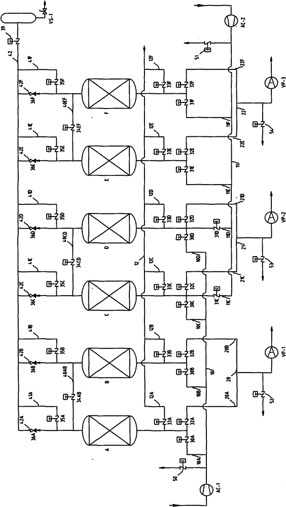
[0052] In order to make the above objects, features and advantages of the present invention more comprehensible, the present invention will be further described in detail below in conjunction with the accompanying drawings and specific embodiments.

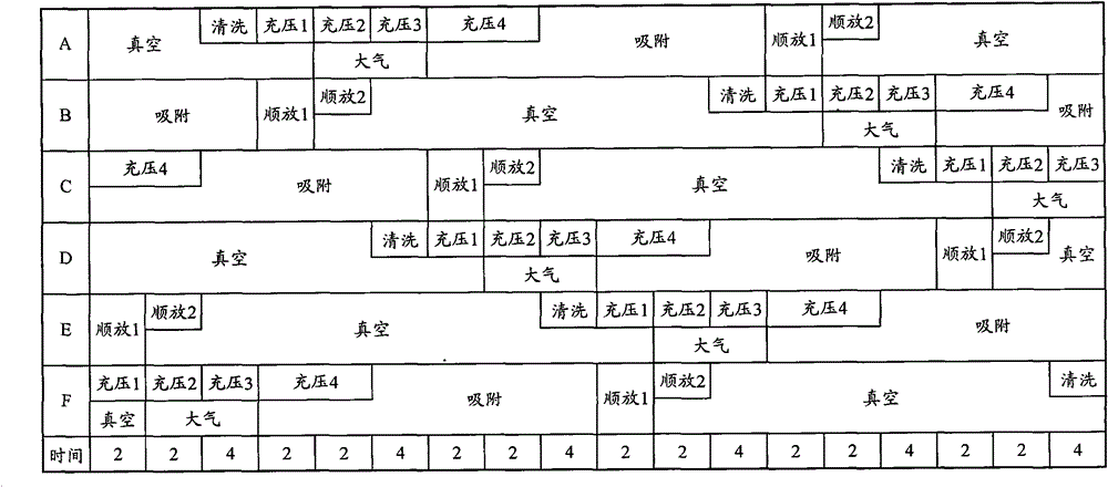
[0053] One of the core ideas of the embodiment of the present invention is to propose a six-tower vacuum pressure swing adsorption system that expands the scale of oxygen production on the basis of reducing system energy consumption and saving costs. This system uses six adsorbers to expand the production capacity. Oxygen scale, and use two sets of independent blowers to continuously deliver compressed air to the adsorber. When the pressure of the adsorber is lower than the atmospheric pressure, the adsorber will also suck raw material air from the atmosphere, thereby reducing the exhaust volume of the blower, which is reasonable Shorten the adsorption time; this system also uses three sets of vacuum pumps to vacuumize the three ad...


PUM


Abstract

The invention provides a vacuum pressure swing adsorption system, which comprises six adsorbers, two groups of independent blowers and three groups of independent vacuum pumps, wherein each group of blowers are connected with the inlet ends of four adsorbers respectively, each group of vacuum pumps are connected with the inlet ends of two adsorbers respectively, the inlet end of each adsorber is communicated with the atmosphere, the outlet ends of the two adsorbers connected with the each group of vacuum pumps are connected, and the outlet end of each adsorber is connected with a product gas tank. The vacuum pressure swing adsorption system cyclically executes the following steps of: adsorption, forward pressure release, vacuum desorption and pressure charge, wherein the ratio of the execution time of the adsorption step to the execution time of the vacuum desorption step is less than 1. The system can enlarge oxygen production scale, reduce the air quantity of the blowers, prolong the vacuum desorption time and reduce the pumping speed of the vacuum pumps so as to reduce energy consumption of the system and save the cost.

Description

technical field [0001] The invention relates to the technical field of pressure swing adsorption air separation, in particular to a vacuum pressure swing adsorption system. Background technique [0002] Vacuum pressure swing adsorption (VPSA for short) system, that is, under the condition of higher than atmospheric pressure, the special molecular sieve for oxygen production by VPSA is used to selectively adsorb impurities such as nitrogen, carbon dioxide and water in the air, and the molecular sieve is desorbed under the condition of vacuuming, so that Oxygen with high purity (90-95%) can be obtained by circulation. [0003] The VPSA system is mainly composed of blower, vacuum pump, switching valve, adsorber and oxygen buffer tank. Raw material air enters the blower after removing dust particles through the suction filter, and enters one of the adsorbers under the blower's conveyance. The adsorber is filled with adsorbent, in which moisture, carbon dioxide, and a small amo...

Claims


Application Information

Patent Timeline
Patent Type & Authority Patents(China)
IPC IPC(8): B01D53/047
Inventor 刘世合姜贺张佳平
Owner BEIJING PEKING UNIV PIONEER TECH
Why Eureka
Try Eureka