
Plate type plasma reactor for hydrogen production through ammonia decomposition

A plasma and reactor technology, applied in the field of plasma chemistry and hydrogen energy, can solve the problems of electronic equipment interference, severe discharge, light column wandering, etc., and achieve the effects of less harmful radiation, increased discharge current density, and stable discharge

Inactive Publication Date: 2010-10-20
DALIAN UNIV OF TECH
View PDF83 Cites 24 Cited by
  • Summary
  • Abstract
  • Description
  • Claims
  • Application Information

AI Technical Summary

Problems solved by technology

The discharge of the latter is violent but unstable, and the beam of light often moves in the discharge area, and the radiation is strong, which seriously interferes with the surrounding electronic equipment.

Method used


Image

  • Plate type plasma reactor for hydrogen production through ammonia decomposition
  • Plate type plasma reactor for hydrogen production through ammonia decomposition
  • Plate type plasma reactor for hydrogen production through ammonia decomposition

Examples


Embodiment 1

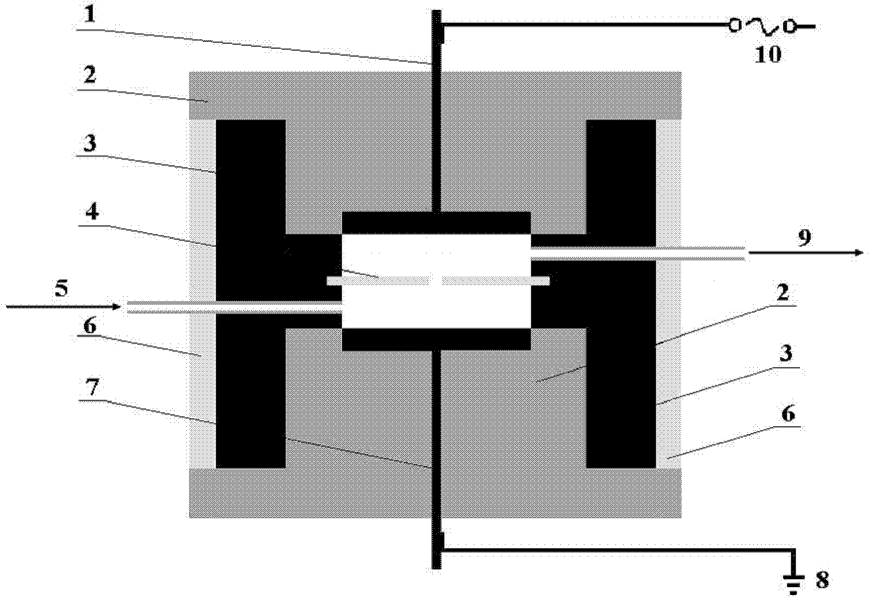
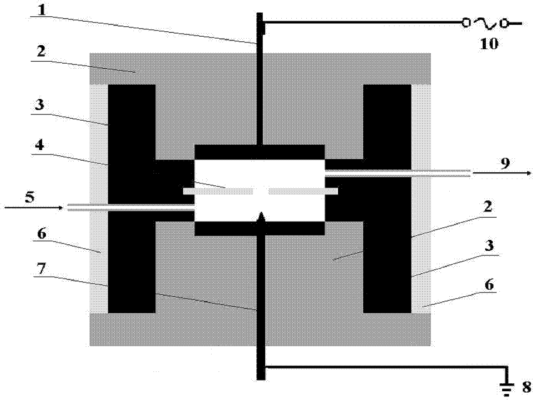
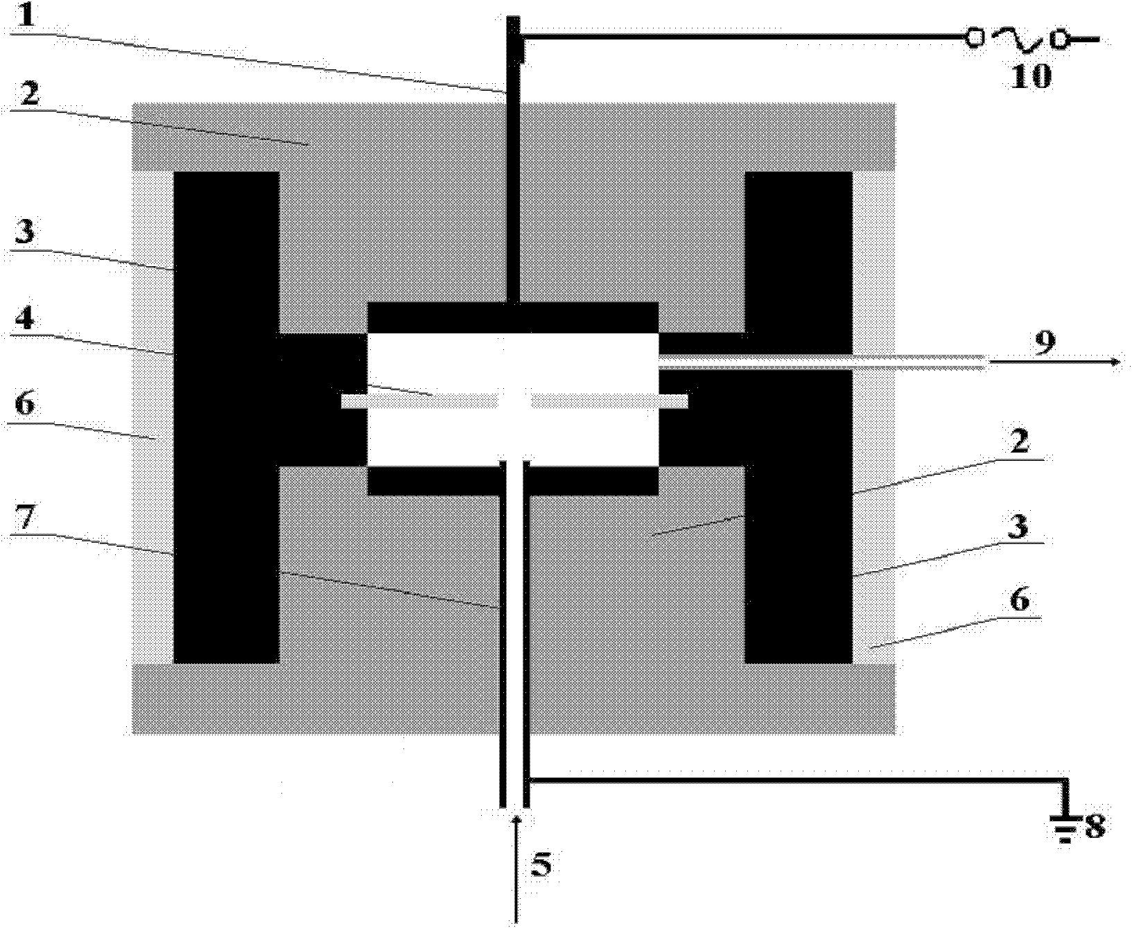
[0069] Anhydrous liquid ammonia is drawn from the storage tank through the pressure reducing valve, and the flow rate of the ammonia gas reaches 40 milliliters / minute through the control of the flow meter and the regulating valve, and the air inlet 5 ( figure 1) into the plate plasma discharge reactor. The metal plate discharge electrodes 1 and 7 of the reactor are made of ordinary stainless steel, with a diameter of 50 mm and a thickness of 3 mm. The insulating seal 2 between it and the reactor shell is made of polytetrafluoroethylene material, and the distance between the two metal electrodes is 4 mm. An insulating barrier dielectric plate with a surface-center opening of 3 mm is placed in parallel between the two metal electrodes. The insulating medium is made of quartz material with a thickness of 1 mm, and the distance from the high-voltage electrode plate and the grounding plate is 1.5 mm. On the reactor wall between the grounding electrode and the barrier medium plate, ...

Embodiment 2

[0071] Example 1 was repeated, but the discharge parameters were set as follows: the initial voltage of the transformer was 70 volts, and the discharge frequency was 13 kHz. Then the power of the high-voltage power supply reaches 21 watts, the actual discharge voltage is 4.9 kV, the temperature of the reactor is stabilized at 139° C. after the reaction is stable, and the ammonia decomposition conversion rate reaches 47%.

Embodiment 3

[0073] Example 1 was repeated, but the discharge parameters were set as follows: the initial voltage of the transformer was 80 volts, and the discharge frequency was 13 kHz. Then the power of the high-voltage power supply reaches 24 watts, the actual discharge voltage is 5.4 kV, the temperature of the reactor is stabilized at 148°C after the reaction is stable, and the ammonia decomposition conversion rate reaches 52%.


PUM

PropertyMeasurementUnit
diameteraaaaaaaaaa
diameteraaaaaaaaaa

Abstract

The invention belongs to the technical field of plasma chemistry and hydrogen energy, and relates to a plate type plasma discharge reactor for hydrogen production through ammonia decomposition. The plasma reactor is characterized by being divided into a plat-plate type, a needle-plate type and a pipe-plate type according to different earth electrodes, wherein an insulating blocking medium is arranged between a high-voltage electrode and the earth electrode of the reactor, and open pores are formed on the blocking medium; the high-voltage electrode and the earth metal electrode generate plasmas to discharge through the open pores on the blocking medium to ensure that ammonia gas is decomposed into hydrogen gas and nitrogen gas in a discharge zone; and the open pores of the blocking medium not only are discharge channels, but also are inevitable channels for reactants. The plate type plasma discharge reactor with the blocking medium provided with the open pores has the advantages of reducing the discharge voltage, limiting the discharge zone, improving the energy density of the discharge zone, and further improving the efficiency of decomposing the ammonia gas directly by using non-equilibrium plasmas.

Description

technical field [0001] The invention belongs to the technical fields of plasma chemistry and hydrogen energy, and relates to a plate-type plasma reactor which can be used for ammonia gas decomposition to produce hydrogen. Background technique [0002] The increasing depletion of fossil energy such as coal, oil and natural gas, and the harm caused by the direct use of these fossil energy to emit greenhouse gases and environmental pollutants force people to continue to pursue clean energy. It is against this background that the development and application of hydrogen energy has attracted worldwide attention. This is because hydrogen gas can be efficiently converted into electricity at almost normal temperature by utilizing a proton exchange membrane fuel cell (PEMFC). What happens during this conversion is a battery reaction of hydrogen and oxygen to form water. The advantages of using hydrogen energy with fuel cells include: (1) Hydrogen and oxygen are not directly burned w...

Claims


Application Information

Patent Timeline
Patent Type & Authority Applications(China)
IPC IPC(8): C01B3/06B01J19/08
CPCY02E60/36
Inventor 郭洪臣赵越王丽宫为民
Owner DALIAN UNIV OF TECH
Learn More