Crank-round slider mechanism, crank shaft thereof and equipment using same

A technology of crank circular sliders and circular sliders, which is applied in the direction of mechanical equipment, crankshafts, machines/engines, etc., can solve problems such as crank pin bending deformation, improve the ability to resist bending deformation, reduce reciprocating inertial force, and improve efficiency Effect

Active Publication Date: 2012-09-26
BEIJING SINOCEP ENGINE TECH
View PDF4 Cites 0 Cited by
  • Summary
  • Abstract
  • Description
  • Claims
  • Application Information

AI Technical Summary

Problems solved by technology

[0010] The invention provides a crank circular slider mechanism to solve the problem of bending and deformation of the crank pin of the crank circular slider mechanism of the existing three circular sliders

Method used


Image

  • Crank-round slider mechanism, crank shaft thereof and equipment using same
  • Crank-round slider mechanism, crank shaft thereof and equipment using same
  • Crank-round slider mechanism, crank shaft thereof and equipment using same

Examples


Embodiment Construction

[0033] In the following description, numerous specific details are set forth in order to provide a thorough understanding of the present invention. However, the present invention can be implemented in many other ways different from those described here, and those skilled in the art can make similar extensions without violating the connotation of the present invention, so the present invention is not limited by the specific implementations disclosed below.

[0034] The crank circular slider mechanism of the present invention will be described in detail below in conjunction with the accompanying drawings.

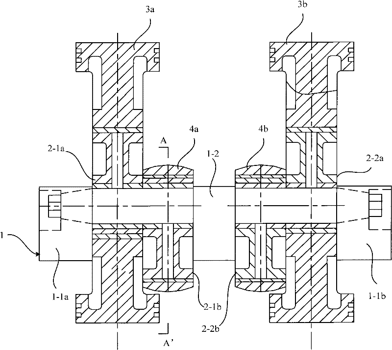
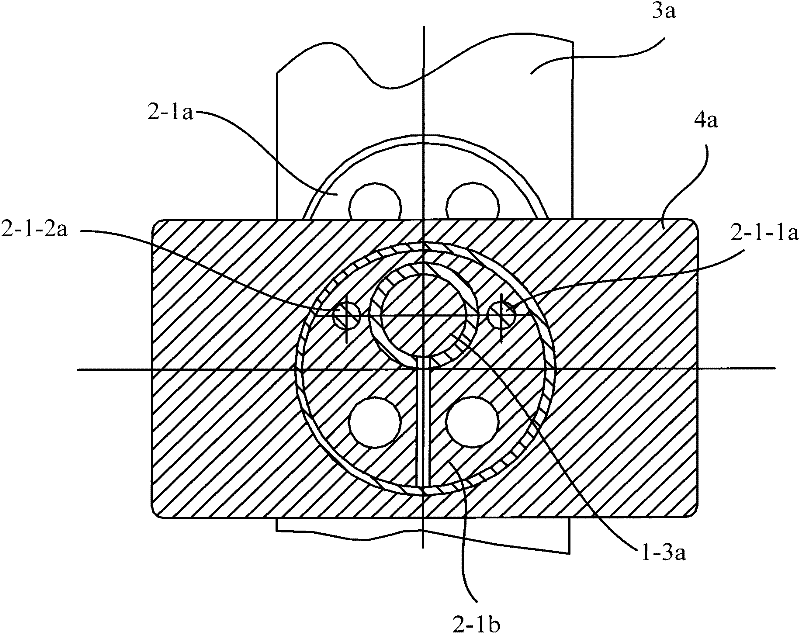
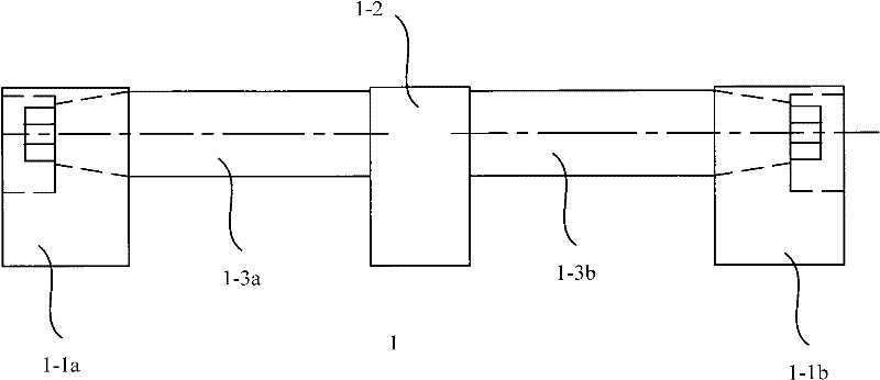
[0035] figure 1 A schematic cross-sectional view of an embodiment of the crank circular slider mechanism provided by the present invention; figure 2 for figure 1 Schematic diagram of the cross-section after splitting along AA'; image 3 for figure 1 Schematic diagram of the crankshaft in .

[0036] Please refer to figure 1 , In the embodiment of the present invention, ...


PUM


Abstract

The invention discloses a crank-round slider mechanism, which comprises round sliders, a reciprocating component, a crank shaft and a machine frame, wherein the crank shaft comprises cranks positioned at two ends and main journals positioned between the two cranks; the cranks and the main journals have a common rotating shaft which is a crank rotating shaft; two coaxial crank pins extend out fromtwo ends of the main journal respectively to the end faces of the two cranks, which face the main journals; the distance between the axes of the two crank pin and the crank rotating shaft is e; the round slider is provided with an eccentric round hole; two round sliders having a phase difference of 180 degrees and fixed together are sleeved on each crank pin and the two round sliders of adjacent main journals have the same phase; the reciprocating component is arranged in a guide rail on the machine frame; each round slider can be rotationally arranged in a round slider accommodating hole of the reciprocating component; the guide rails of the reciprocating component corresponding to the round sliders with the same phase are arranged in parallel; and the guide rails of the reciprocating component corresponding to the round sliders with the phase difference of 180 degrees are vertical to each other. The mechanism of the invention can improve the bending resistance and deformation resistance of the crank shaft so that the stability of the mechanism is effectively improved. The invention also provides the crank shaft of the crank-round slider mechanism and equipment using the mechanism.

Description

technical field [0001] The invention relates to a mechanism for mutual conversion between reciprocating motion and rotary motion, in particular to a crank circular slider mechanism. The invention also relates to a crankshaft of the crank circular slider mechanism and a device using the mechanism. Background technique [0002] In conventional internal combustion engines and compressors, the conversion between the reciprocating motion of the piston and the rotational motion of the crankshaft is achieved by a crank-and-rod mechanism. However, due to the existence of the connecting rod, the internal combustion engine and compressor of the crank linkage mechanism have disadvantages such as bulky, heavy, and poor balance performance. [0003] In order to solve the problems referred to above, the Chinese patent whose approval announcement date is January 13, 1988 and whose announcement number is CN85100358B discloses a kind of "crank circular slider reciprocating piston internal c...

Claims


Application Information

Patent Timeline
Patent Type & Authority Patents(China)
IPC IPC(8): F16H21/18F16H37/12F16C3/08F02B75/32
Inventor 黎明黎正中
Owner BEIJING SINOCEP ENGINE TECH
Why Eureka
Try Eureka