High-efficiency large polycrystalline silicon reducing furnace

A technology of polysilicon and reduction furnace, which is applied in the growth of polycrystalline materials, silicon, single crystal growth, etc., can solve the problems of uneconomical, large and unreasonable volume of the furnace drum in the area of ​​the chassis, and achieve the reduction of production power consumption and cost, and effective Conducive to shape control and the effect of ensuring product quality

Inactive Publication Date: 2010-10-27
JIANGSU ZHONGNENG POLYSILICON TECH DEV
View PDF4 Cites 23 Cited by
  • Summary
  • Abstract
  • Description
  • Claims
  • Application Information

AI Technical Summary

Problems solved by technology

Among them, 36 pairs of rod reduction furnaces will arrange another layer of 12 pairs of rods on the basis of 24 pairs of rods, which makes the number of rod pairs in the outermost ring and the second outer ring the same, which is obviously uneconomical and wastes a lot of space
The 48-pair rod reduction furnace will arrange another layer of 24 pairs of rods or a combination of a layer of 16 pairs of rods and a layer of 8 pairs of rods in the outermost circle on the basis of 24 pairs of rods. In some cases, the silicon rods are arranged too densely in the outer ring; the latter arrangement obviously wastes most of the space in the outermost layer, which is very unreasonable
A 60-pair rod reduction furnace needs to add a ring of 16 pairs and a ring of 20 pairs of rods to the outer ring of 24 pairs of rods. Although this can form a neat arrangement, due to the formation of a 5-layer electrode arrangement, the area of ​​the chassis and the furnace tube The volume is too large, which is not conducive to safe and stable production

Method used


Image

  • High-efficiency large polycrystalline silicon reducing furnace
  • High-efficiency large polycrystalline silicon reducing furnace
  • High-efficiency large polycrystalline silicon reducing furnace

Examples


Embodiment Construction

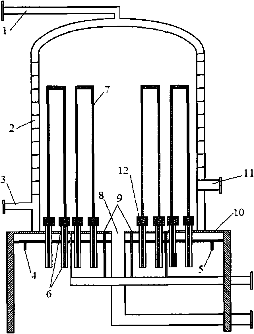
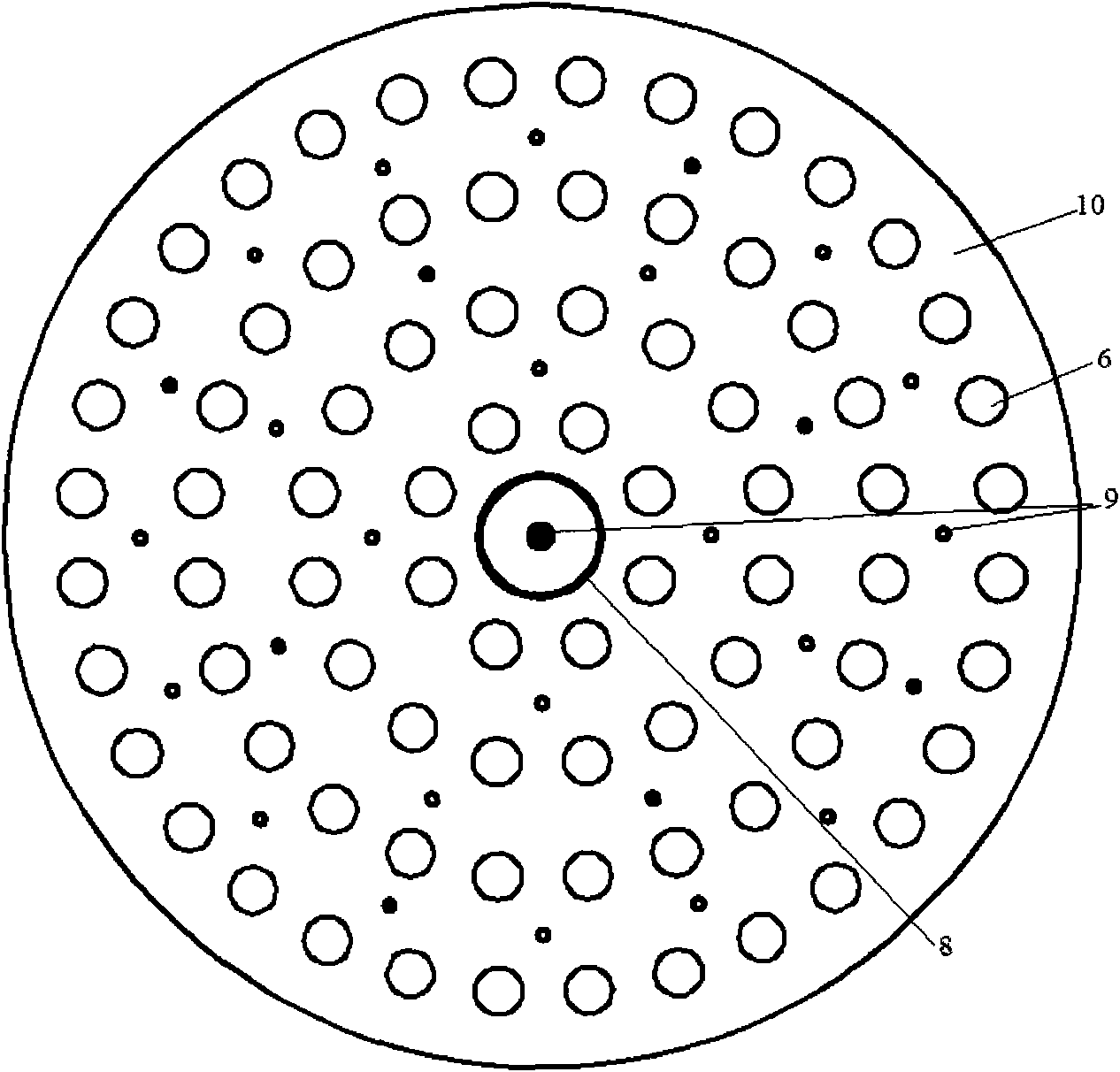
[0031] Such as figure 1 In the conventional polysilicon reduction furnace shown, the chamber surrounded by the chassis 10 and the reduction furnace drum 2 with cooling jacket constitutes the space for chemical vapor deposition reaction, wherein the lower part of the reduction furnace drum 2 with cooling jacket is provided with Furnace cylinder cooling water supply pipe 3, furnace cylinder cooling water return pipe 1 is provided at the top of furnace cylinder 2, chassis cooling water supply pipe 4 and chassis cooling water return pipe 5 are respectively provided at the lower part of chassis 10, and an observation port is provided at the lower part of furnace cylinder 2 11. There are many pairs of electrodes 6, a plurality of air inlets 9 and an air outlet 8 evenly arranged on the surface of the chassis 10. The copper plate of the electrode is connected to the power supply (not shown) through the bus bar, and the silicon core 7 is housed on the electrode and passed through The ...


PUM

PropertyMeasurementUnit
diameteraaaaaaaaaa
diameteraaaaaaaaaa
heightaaaaaaaaaa

Abstract

The invention discloses a high-efficiency large polycrystalline silicon reducing furnace which comprises a chassis and a bell type furnace barrel, wherein the bell type furnace barrel covers the chassis, and a plurality of pairs of electrodes, at least one air inlet and at least one exhaust port are closely arranged on the chassis. The high-efficiency large polycrystalline silicon reducing furnace is characterized in that the pair number of the electrodes is 2n(n+1), wherein n is the distributed layer number of the electrodes and is not less than 4, and the 2n(n+1) pairs of electrodes are arranged in n layers and regularly arranged according to 4n pairs, such as 4 pairs, 8 pairs, 12 pairs and the like in each layer. The more dense and regular electrode arrangement is realized by a reactor, the utilization ratio of the heat energy in the reducing furnace is improved, and more uniform flow field distribution is realized, thereby improving the polycrystalline silicon yield of each furnace, improving the product surface quality and reducing the energy consumption.

Description

technical field [0001] The invention relates to the field of high-purity silicon preparation, in particular to a reduction furnace for preparing polysilicon by an improved Siemens process. Background technique [0002] At present, polysilicon production mainly adopts improved Siemens process. The principle of the so-called Siemens process is to use high-purity hydrogen (H 2 ) reduction of high-purity trichlorosilane (SiHCl 3 ), generating polysilicon deposited on the silicon core. The improved Siemens process is based on the Siemens process, adding a reduction tail gas dry recovery system, silicon tetrachloride (SiCl 4 ) hydrogenation process to achieve closed-circuit circulation, and reduce the energy consumption per unit of product by using a large reduction furnace. [0003] The improved Siemens process mainly uses a bell-type reactor (also known as a reduction furnace) and a silicon core connected to an electrode as a deposition substrate, using a high-temperature re...

Claims


Application Information

Patent Timeline
Patent Type & Authority Applications(China)
IPC IPC(8): C01B33/03C30B29/06
Inventor 严均
Owner JIANGSU ZHONGNENG POLYSILICON TECH DEV
Why Eureka
Try Eureka