
Method for processing sludge pyrolytic oil

A processing method and pyrolysis oil technology, applied in the direction of hydrocarbon oil dehydration, vacuum distillation, etc., can solve the problems of reducing particle concentration, high cost, affecting other properties of oil, etc., and achieve the effect of simple operation and low cost

Inactive Publication Date: 2010-11-03
TIANJIN UNIV
View PDF1 Cites 7 Cited by
  • Summary
  • Abstract
  • Description
  • Claims
  • Application Information

AI Technical Summary

Problems solved by technology

[0004] Because sludge pyrolysis oil is very different from petroleum in terms of properties, pyrolysis oil contains a large amount of light components and heavy components, and the properties of pyrolysis oil are unstable, some people in foreign countries increase the oil quality by adding methanol. properties, but the addition of solvents only reduces the concentration of particulate matter, not the number, and also affects other properties of the oil, so it is not an ideal modification method
Although catalytic cracking can improve the quality of pyrolysis oil, the cost is high
[0005] Looking at the existing sludge pyrolysis oil processing methods, the existing problems are the high cost of the processing process and the difficulty in obtaining high-performance oil products

Method used


Image

  • Method for processing sludge pyrolytic oil
  • Method for processing sludge pyrolytic oil

Examples


Embodiment 1

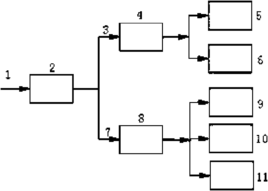
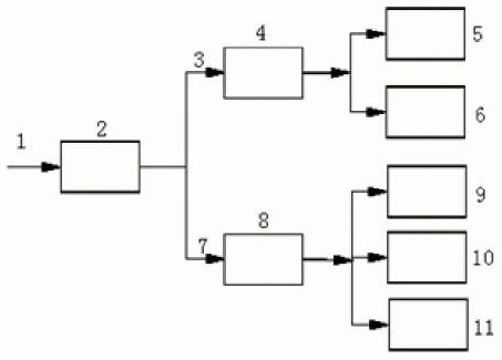
[0019] Such as figure 1 As shown, the sludge pyrolysis oil 1 is introduced into the distillation dehydration device 2. The device 2 is connected with a temperature measuring and condensing device (not shown in the figure), and the condensing medium is cold water at about 20°C (not shown in the figure). Turn on the electric heater, and as the temperature rises, substances in the oil continue to volatilize until the temperature rises to 120-140°C. Reduce the heating power and keep the temperature for 1-3 minutes to ensure that all the water is evaporated. The steamed water and The mixture 3 of gasoline-like components is recycled to the multi-production outlet separation device 4 through condensation (this separator is placed vertically and statically, which can prevent oil and water from remixing), and water 5 and gasoline-like components 6 are obtained through separation. The residual oil 7 after dehydration in the kettle is introduced into the evaporation kettle of the vacuum...

Embodiment 2

[0022] The treatment process is basically the same as in Example 1, except that the vacuum distillation unit 8 is a continuous operation unit. After dehydration, the remaining oil 7 is continuously introduced into the vacuum distillation tower, the diesel-like component 9 is extracted from the tower top and the waxy component 10 is simultaneously extracted from the tower, and the residual oil 11 is discharged from the bottom of the tower.

[0023] According to Example 2, pyrolysis oil 1 can be cut by fractions to obtain about 25% of 5, about 15% of gasoline-like component 6, about 30% of diesel-like component 9, about 10% of waxy component 10, and residual oil 11 About 20%, of which gasoline-like component 6 and diesel-like component 9 can be directly used as vehicle oil, waxy component 10 can be used as other chemical raw materials, and residual oil 11 can be used as asphalt.


PUM


Abstract

The invention relates to a method for processing sludge pyrolytic oil, comprising the following steps: 1) distilling and dewatering sludge pyrolytic oil containing water; 2) separating the distilled water and quasi-gasoline components; and 3) performing reduced pressure distillation on the dewatered oil to obtain fractions at different temperature stages. Oily matters generated by sludge pyrolysis is distilled and dewatered in a distiller, and the distillation condition is that water in the pyrolytic oil is distilled out at the temperature of 120-130 DEG C maintained for 1-3min. A dewatering and distilling device, a continuous or intermittent reduced pressure distillation device and a vacuum receiving and separating device utilized in the invention all can adopt equipment used in the raw oil processing procedure, as long as the requirements of dewatering, reduced pressure distillation and receiving and separating fractions can be satisfied. The method provided by the invention has simple operation and low cost, and provides necessary conditions for subsequent high performance fuel applications.

Description

technical field [0001] The invention relates to a processing method of sludge pyrolysis oil, in particular to a dehydration and post-processing method of water-containing sludge pyrolysis oil. Background technique [0002] With the rapid development of urbanization and stricter environmental protection, there are more and more municipal sewage treatment plants, and the sludge output has also increased sharply. How to deal with sludge from sewage plants has become a worldwide problem. In order to reduce the cost of treatment, countries are paying more and more attention to the resource utilization of sludge. At the same time, with the depletion of fossil fuels, biomass has become the most potential alternative energy source. As a kind of biomass energy, sludge is also a new topic of renewable energy. [0003] At present, the technical direction of sludge treatment and resource utilization mainly includes fermentation to produce gas, as fertilizer, gasification and pyrolysis,...

Claims


Application Information

Patent Timeline
IPC IPC(8): C10G7/04C10G7/06
Inventor 张书延姬爱民
Owner TIANJIN UNIV
Learn More