Magnetoconductive ring

A technology for magnetically permeable rings and magnetic gathering, applied in the field of magnetically permeable rings

Inactive Publication Date: 2013-01-02
HANGZHOU SES MACHINERY
View PDF3 Cites 0 Cited by
  • Summary
  • Abstract
  • Description
  • Claims
  • Application Information

AI Technical Summary

Problems solved by technology

[0005]However, there are some insurmountable shortcomings in the photoelectric encoder: the photoelectric encoder is made of glass material through the engraved lines, and its anti-vibration and impact ability is not strong, so it is not suitable for In severe environments such as dust and condensation, and the structure and positioning assembly are complicated; the distance between the engraved lines is limited, and the code disc must be enlarged to improve the resolution, so it is difficult to achieve miniaturization; high assembly accuracy must be ensured in production. Directly affect production efficiency and ultimately affect product cost
[0009]The inner side of the stator is generally arc-shaped and smooth, the sensor is not easy to install and fix, it is easy to cause positioning error, and then cause the phase deviation of the signal, making the high-order harmonic component in the signal large ; The processing and manufacturing process is complicated, which is not conducive to industrialization;
[0010] has low reliability, the sensors are evenly distributed on the inner wall, and the supporting substrate of the sensor must be a flexible body such as FPC, etc., and its tensile strength is not high at the contact with the processing body , easy to break, increasing the difficulty of processing and affecting the life of the product;
[0011]The leakage of the magnetic field induced by the sensor is large, and the magnetic field cannot be fully applied, resulting in large noise in the signal and affecting the measurement accuracy;
[0012] requires the sensor to be small in size, which makes the product cost relatively high

Method used


Image

  • Magnetoconductive ring
  • Magnetoconductive ring
  • Magnetoconductive ring

Examples


Embodiment

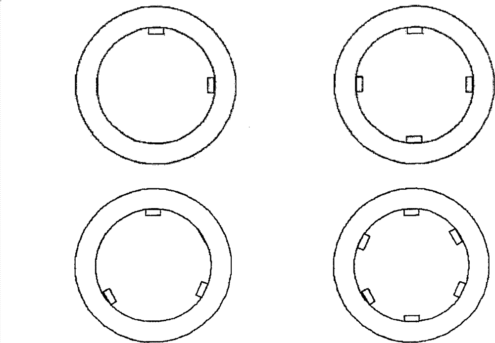
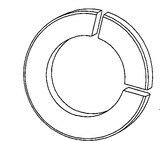
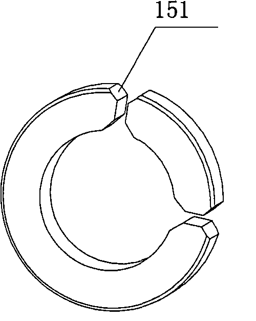
[0029] Figure 2A ~ Figure 2D It is the chamfering design drawing of the magnetic permeable ring of the present invention. Such as Figure 2A ~ Figure 2D As shown, the magnetic permeable ring is composed of two or more arc segments with the same radius and the same center. Figure 2A The magnet ring shown is not designed with chamfers, Figure 2B ~ Figure 2D The end of the arc section shown is provided with a chamfer, and the chamfer is along the axial direction ( Figure 2B ) or radial ( Figure 2C ) or both axially and radially ( Figure 2D ) chamfer formed by cutting, 151, 153 represent the axial section, 152, 154 represent the radial section. There is a gap between two adjacent arc segments, and the magnetic induction element is placed in the gap. When the magnetic steel ring and the magnetic permeation ring rotate relative to each other, the magnetic induction element converts the sensed magnetic signal into a voltage signal, and This voltage signal is transmitted t...


PUM


Abstract

A magnetically conductive ring is provided, which consists of two or more arc segments with same radius and center, the adjacent arc segments are provided with an air gap. The homogeneous distribution of the magnetic field inside the magnetically conductive ring, the minor flux leakage, the integral type signal inducted by the magnetic field sensitive component, the small signal noise and the component ingredient of the contained ultraharmonics and the improved original signal quality and the signal noise ratio can be achieved through adopting this structure of the magnetically conductive ring. Also, there is no strict requirements to the mechanical dimension of the magnetic field sensitive component and the wider types can be chosen, even the follow-up amplifying circuit can be omitted. So this structure is benefit to the reduced product cost and raised cost performance ratio.

Description

technical field [0001] The invention relates to a magnetic element, in particular to a magnetic conducting ring. Background technique [0002] The position detection device used in the field of motor control is mainly an encoder. The encoder is a position sensor that converts physical quantities such as the rotational angular position and angular velocity of the motor into electrical signals. The manufacture and signal processing level of the encoder directly affect level of automation. [0003] At present, the encoders used in the field of engineering technology are mainly photoelectric encoders, and there are two types of photoelectric encoders: incremental and absolute. In an incremental encoder, when the shaft rotates, the grating disk is driven to rotate, and the light emitted by the light-emitting element is cut into intermittent light by the slit of the grating disk, and then the receiving element receives and outputs the corresponding pulse signal, rotation directio...

Claims


Application Information

Patent Timeline
Patent Type & Authority Patents(China)
IPC IPC(8): H01F3/00H01F3/14H01F41/02
CPCG01D5/145G01D2205/40
Inventor 郝双晖郝明晖
Owner HANGZHOU SES MACHINERY
Why Eureka
Try Eureka