Current collector of liquid flow battery and liquid flow battery

A liquid flow battery and current collector technology, applied in battery electrodes, electrode carriers/current collectors, fuel cells, etc., can solve the problems of easy detachment of electrode mats, high cost, and large contact resistance

Active Publication Date: 2010-11-03
BYD CO LTD
View PDF0 Cites 32 Cited by
  • Summary
  • Abstract
  • Description
  • Claims
  • Application Information

AI Technical Summary

Problems solved by technology

[0005] The purpose of the present invention is to overcome the defects of the prior art that the current collector of the liquid flow battery is easily broken, the cost is high, the contact resistance is large, and the electr

Method used


Image

  • Current collector of liquid flow battery and liquid flow battery
  • Current collector of liquid flow battery and liquid flow battery
  • Current collector of liquid flow battery and liquid flow battery

Examples


preparation example Construction

[0021] The preparation method of the current collector provided by the invention comprises hot pressing a graphite plate on the surface of a conductive plastic plate. The hot pressing can be performed using various conventional hot pressing machines, for example, a SYR-100T hot pressing machine from Dongguan Shangyu Oil Pressure Machinery Factory can be used. The temperature of hot pressing can be 200-500°C, preferably 320-400°C; the pressure of hot pressing can be 50-250Kg / cm 2 , preferably 150-200Kg / cm 2 , the time of hot pressing can be 5-60 minutes, preferably 25-45 minutes.

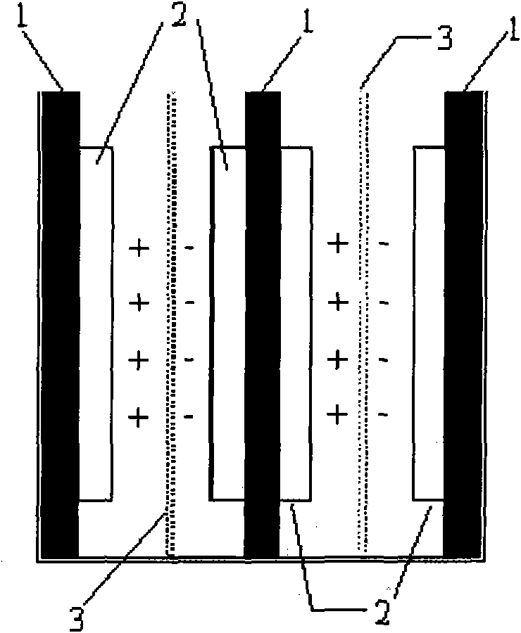
[0022] The liquid flow battery also provided by the present invention includes two end plates, a plurality of electrode plates, a positive electrode electrolyte, a negative electrode electrolyte and a plurality of diaphragms, and the plurality of electrode plates, the positive electrode electrolyte, the negative electrode electrolyte and a plurality of diaphragms are arranged Between the two end pl...

Embodiment 1

[0033] This example is used to illustrate the current collector of the flow battery provided by the present invention.

[0034] A conductive plastic plate of 200×200×2mm was polished by sandblasting, washed with dilute sulfuric acid (concentration 2mol / L) and deionized water in sequence, and then dried in a drying room for 0.5 hours. A 140×140×0.8mm flexible graphite plate (Yichang Xincheng Graphite Co., Ltd.) was polished by sandblasting, washed with dilute sulfuric acid (concentration 2mol / L) and deionized water in turn, and then placed in a drying room Dry in medium for 10min.

[0035] Wherein, the preparation method of conductive plastic plate is as follows:

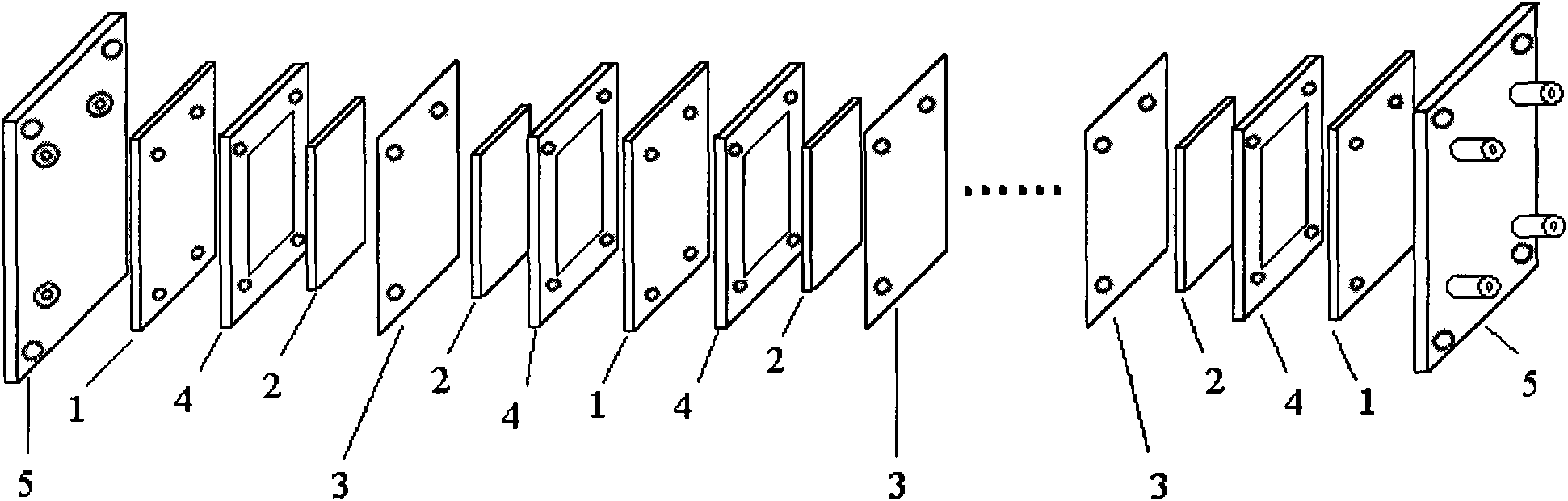
[0036] Equipped with exhaust device, and the size is 34mm×34mm×40mm Figure 5 Shown flat-bottomed reactor (the inner space of reactor is made of base 51 and bell-shaped loam cake 52; On described bell jar-shaped loam cake 52, be equipped with exhaust port 53, through this exhaust port The operation of vacuumizing ...

Embodiment 2

[0039] This example is used to illustrate the current collector of the flow battery provided by the present invention.

[0040] Prepare the current collector of the flow battery in the same manner as in Example 1, except that the size of the flexible graphite plate is 130×130×0.3 mm, and the distance between the edge of the flexible graphite plate and the edge of the conductive plastic plate is 35 mm; and it is conductive The preparation method of the plastic plate is: mix polyethylene and graphite powder at a weight ratio of 1:1 at 40°C for 60 minutes; Plastic plates.

[0041] The current collector of the unipolar plate and the current collector of the bipolar plate are respectively denoted as A21 and A22.


PUM

PropertyMeasurementUnit
Volume resistivityaaaaaaaaaa
Thicknessaaaaaaaaaa
Thicknessaaaaaaaaaa

Abstract

The invention provides a current collector of a liquid flow battery. The current collector comprises a conductive plastic plate and a graphite plate attached to the surface of the conductive plastic plate, wherein the area of the graphite plate is 20 to 90 percent of that of the conductive plastic plate; and the edges of the graphite plate are all positioned in the surface of the conductive plastic plate. The invention also provides the liquid flow battery, which comprises the current collector provided by the invention. Because conductive plastic has high toughness, elasticity and corrosion resistance, the current collector only comprising the graphite plate is prevented from being broken due to concentrated stress during processing; and the graphite plate is integrated with a conductivepart on the surface of the conductive plastic plate so as to increase effective current path. Therefore, the current collector of the liquid flow battery solves the problems of detachment of an electrode felt and high contact resistance in a using process.

Description

technical field [0001] The invention relates to a current collector of a flow battery and a flow battery comprising the current collector. Background technique [0002] Flow battery is a new type of environmentally friendly energy storage system, which is an electrochemical system that uses oxidation-reduction reactions of elements with different valence states for energy storage and conversion. Compared with other energy storage systems, flow batteries have the advantages of high current charge and discharge, high overall energy efficiency, and large-scale application. For example, with V 5+ / V 4+ and V 3+ / V 2+ The redox flow battery in which the electric pair is used as the positive and negative active materials of the battery is called an all-vanadium redox flow battery, or vanadium flow battery for short. The electrode active material of the vanadium redox flow battery is a sulfuric acid solution containing vanadium, and the positive electrode electrolyte contains ...

Claims


Application Information

Patent Timeline
IPC IPC(8): H01M4/66H01M8/18H01M10/36H01M8/02H01M4/96H01M8/0228H01M8/0245
CPCY02E60/12Y02E60/528Y02E60/10Y02E60/50
Inventor 张一帆李世彩葛菲
Owner BYD CO LTD
Why Eureka
Try Eureka