Multi-section servo submersible motor

A submersible motor and motor shaft technology, applied in the field of servo motors, can solve the problems of low motor efficiency and power factor, low oil production cost, low system efficiency, and low system efficiency.

Inactive Publication Date: 2010-11-03
杭州坤泽采油设备有限公司
View PDF1 Cites 19 Cited by
  • Summary
  • Abstract
  • Description
  • Claims
  • Application Information

AI Technical Summary

Problems solved by technology

[0003] First, when it is matched with the centrifugal submersible pump, because the motor speed is lower than the synchronous speed, the motor efficiency and power factor are low;
[0004] Second, when it is matched with the submersible screw pump, the speed is too high to reduce the speed to the speed suitable for the screw pump through the tachometer. Even if the reducer is used, the cost of oil production will be greatly increased and the efficiency of the system will be reduced. The frequency conversion speed control device is used to keep the motor in a low-frequency working state for a long ti

Method used


Image

  • Multi-section servo submersible motor
  • Multi-section servo submersible motor
  • Multi-section servo submersible motor

Examples


Embodiment 1

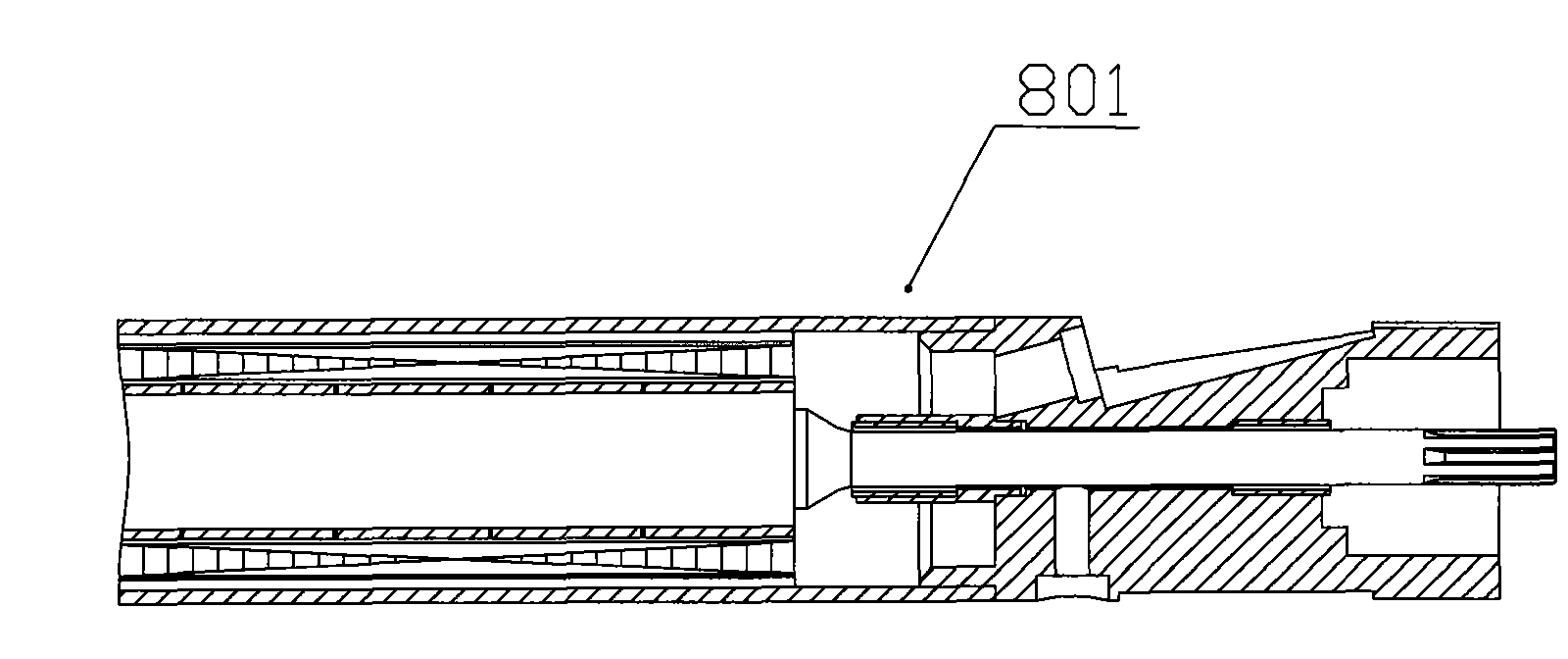
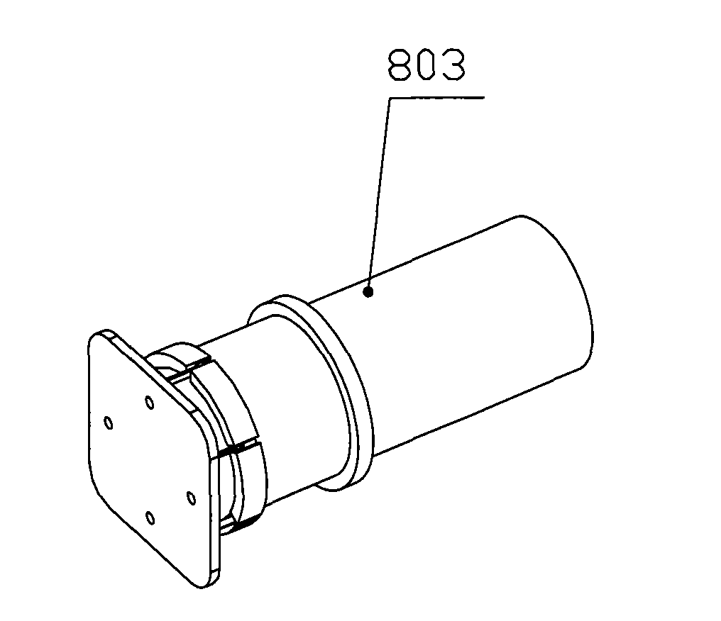
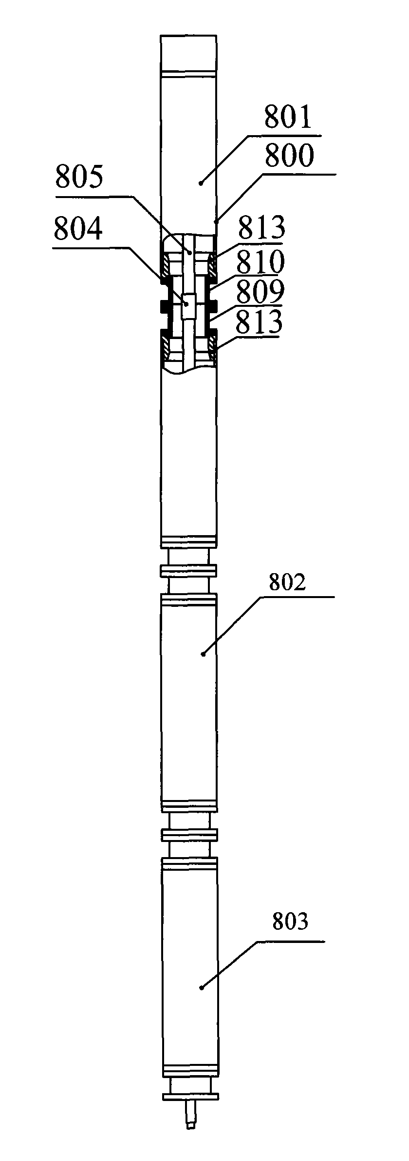
[0125] figure 1 , figure 2 They are respectively the internal structure schematic diagrams of the first section and the last section of the present invention. combine image 3 As shown, in order to solve the above problems, the present invention provides a permanent magnet synchronous servo motor in a multi-section form, in order to provide greater power. image 3 It is a schematic diagram of permanent magnet synchronous servo submersible motor with four motors connected by threads and flanges. Figure 4 It is the three-dimensional structure diagram of the permanent magnet synchronous servo submersible motor. The first section motor 801 is at the top of the whole servo motor, and has a motor head (not shown) that is used to connect with the protector; the last section motor 803 is the last section of the servo motor, and the tail is equipped with a motor tail shaft, which is used to install the magnet. The steel ring, the lower flange 810 is connected with the sealing dev...

Embodiment 2

[0127] refer to Figure 5 , Figure 6 It is a schematic diagram of the assembly structure of the permanent magnet synchronous servo submersible motor according to the second embodiment of the present invention. In this embodiment, most of the structures are the same as those in Embodiment 1, and the same structures will not be described again. The difference is that in this embodiment, the middle of every two motors is connected by bolts, and the upper flange and the lower flange are connected to the motor housing by bolts. This form is suitable for the situation when the motor casing is thick enough to screw on the bolts.

Embodiment 3

[0129] refer to Figure 7 , Figure 8 It is a schematic diagram of the assembly structure of the permanent magnet synchronous servo submersible motor according to the third embodiment of the present invention. In this embodiment, most of the structures are the same as those in Embodiment 1, and the same structures will not be described again. The difference is that in this embodiment, every two sections are connected in the middle by bolts. The upper threaded flange 811, the lower threaded flange 812 and the motor housing 800 are connected by threads; the upper threaded flange 811, the lower threaded flange 812 are connected by bolts, and a wide nut 814 is installed on the upper threaded flange 1. Narrow nut 815 two movable nuts, after adjusting the positions of each section of the motor during assembly, complete the assembly of the motor by tightening the two nuts 814, 815, which can prevent the rotation between each section of the motor.

[0130] The two submersible motor...


PUM


Abstract

The invention relates to a multi-section servo submersible motor which mainly comprises a motor body, wherein a motor housing at the head of the motor body is connected with a head flange, the head of a motor shaft convexly extends out of the head flange, the motor shaft is fixed in the head flange and is connected with other devices through the head flange, the motor body internally comprises multiple sections of motors, the motor housing of each section of motor internally mainly comprises a stator and a rotor, the rotor is a permanent magnet, a winding is arranged in a stator iron core, rotor shafts of two adjacent sections of motors are connected through a coupler; the motor housings of two adjacent sections of motors are connected through a connecting device; N poles of the rotors arranged on two adjacent sections of motors correspond in a straight line and S poles correspond in a straight line; and U, V and W phase windings of the rotors respectively correspond in a straight line. The servo submersible motor has simple installation structure, easy operation and capability of providing higher power.

Description

technical field [0001] The utility model relates to a servo motor, in particular to a multi-section servo submersible motor with improved motor structure. Background technique [0002] At present, in my country and other oil-producing countries in the world, submersible motors are widely used in oilfields to drive submersible electric pumps to draw crude oil. The power source of traditional electric submersible pump systems is mainly two-pole three-phase asynchronous motors. There are three problems in the oil recovery system in the process of oil recovery: [0003] First, when it is matched with the centrifugal submersible pump, because the motor speed is lower than the synchronous speed, the motor efficiency and power factor are low; [0004] Second, when it is matched with the submersible screw pump, the speed is too high to reduce the speed to the speed suitable for the screw pump through the tachometer. Even if the reducer is used, the cost of oil production will be gre...

Claims


Application Information

Patent Timeline
IPC IPC(8): H02K16/00H02K11/00G01D5/249
CPCH02K16/00H02K5/132
Inventor 郝双晖郝明晖
Owner 杭州坤泽采油设备有限公司
Why Eureka
Try Eureka