Catalytic combustion heat recovery system and method

A catalytic combustion and heat recovery technology, applied in lighting and heating equipment, dryers, drying, etc.

Inactive Publication Date: 2010-11-10
上海联净环保科技有限公司
View PDF0 Cites 8 Cited by
  • Summary
  • Abstract
  • Description
  • Claims
  • Application Information

AI Technical Summary

Problems solved by technology

[0004] The purpose of the present invention is to provide a catalytic combustion heat recovery treatment system to overcome the waste of heat so

Method used


Image

  • Catalytic combustion heat recovery system and method
  • Catalytic combustion heat recovery system and method
  • Catalytic combustion heat recovery system and method

Examples


Embodiment Construction

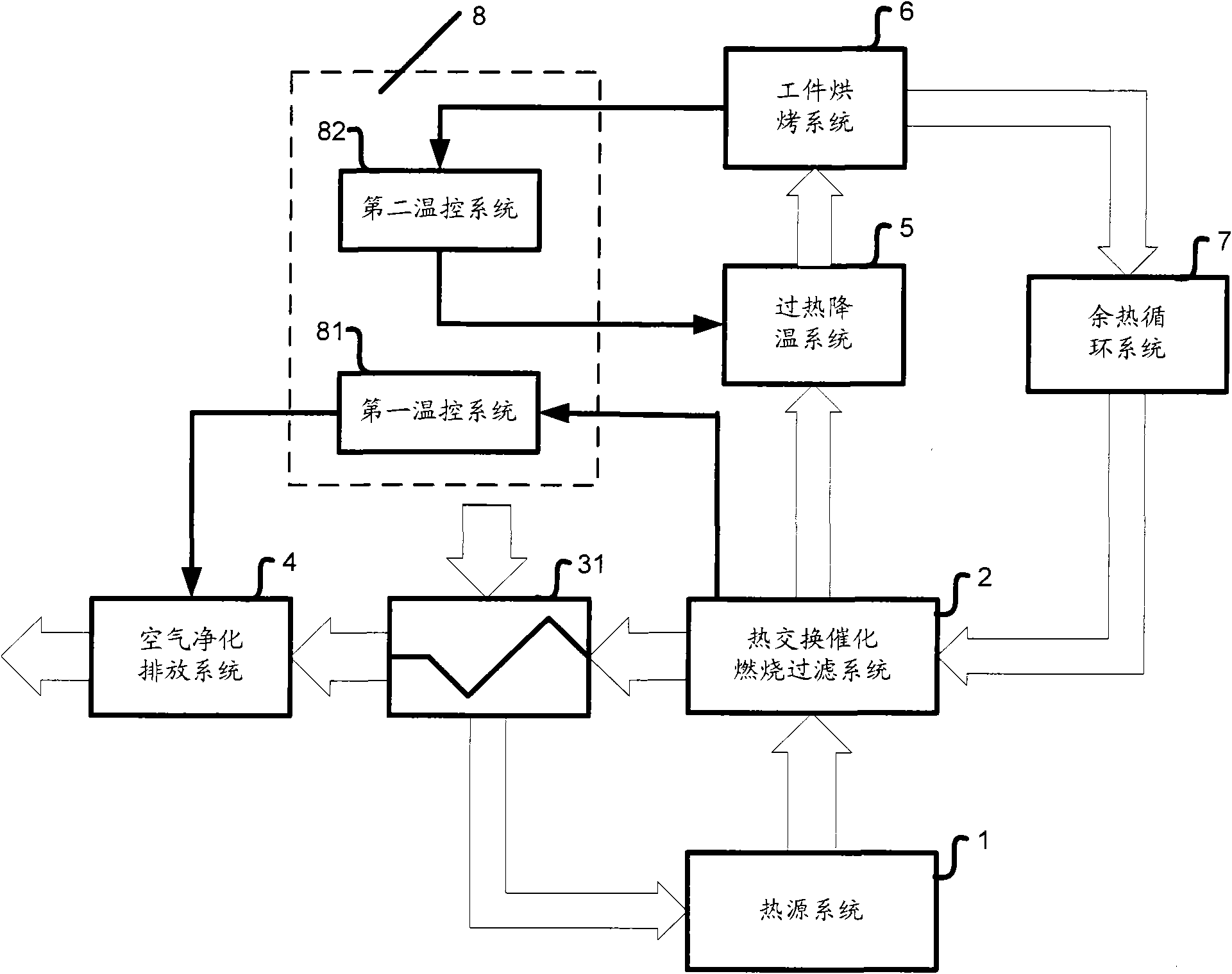
[0028] figure 1 A schematic structural diagram of a catalytic combustion heat recovery system according to the first embodiment of the present invention is shown. Specifically, in this embodiment, the catalytic combustion heat recovery system includes a heat source system 1, a heat exchange catalytic combustion filter system 2, a first heat exchange system 31, an air purification exhaust system 4, an overheating and cooling system 5, and a workpiece baking System 6, waste heat circulation system 7 and temperature control system 8. More specifically, in this embodiment, the catalytic combustion heat recovery system includes a first hot air circuit and a second hot air circuit, wherein the first hot air circuit is an open loop, which is mainly composed of the heat source system 1 , the heat exchange catalytic combustion filter system 2, the first heat exchange system 31 and the air purification discharge system 4 constitute; the second hot air circuit is a closed loop circuit, ...


PUM


Abstract

The invention provides a catalytic combustion heat recovery system which comprises a heat source system, an air purifying and discharging system, a workpiece baking system, a heat-exchange catalytic-combustion filtering system, a waste heat circulating system and a temperature control system. Preferably, the catalytic combustion heat recovery system also comprises an overheating cooling system. The invention also provides a heat recovery control method of the catalytic combustion heat recovery system. In the invention, energy sources can be fully utilized by recycling the waste heat of waste gas, thereby performing the effect of environmental protection and avoiding the waste of the heat carried by tail gas still with higher temperature. According to the catalytic combustion heat recovery system, the expenses on a traditional heating system can be reduced by 60-90 percent, and organic gas, such as triphenyl, ester, ketone, ether, aldehyde, phenol and the like in a baking oven body can be recovered to enter the heat-exchange catalytic-combustion filtering system for catalytic combustion processing and resent into the baking oven body for cyclic utilization, thereby reducing environmental pollution, fully exerting the value of the energy sources and reducing the loss of the energy sources.

Description

technical field [0001] The invention relates to a heat recovery system, in particular to a catalytic combustion heat recovery system used in coating and drying industries. Background technique [0002] Coating, drying, and baking are relatively traditional industries. With the development of the economy, the market demand is also increasing, so the scale of these industries is constantly expanding, and the technology of related equipment is constantly being updated. However, the problem of high energy consumption in these industries is becoming more and more prominent, especially with the continuous fluctuation and high price of oil, natural gas, coal and electricity, the energy consumption expenditure of various coating and drying enterprises is increasing. bigger. On the one hand, during the baking process, the organic solvent in the paint will volatilize organic gases, such as formaldehyde, benzine, toluene and xylene. If the organic gases are directly discharged into t...

Claims


Application Information

Patent Timeline
IPC IPC(8): F26B21/04F26B21/10
CPCY02P70/10
Inventor 文元庆邹斌向燕龙刘永民
Owner 上海联净环保科技有限公司
Why Eureka
Try Eureka