Power factor correction converter based on magnetic coupling lossless buffer circuit

A power factor correction and buffer circuit technology, which is applied to output power conversion devices, high-efficiency power electronic conversion, electrical components, etc. The effect of reducing switching loss, improving efficiency, and suppressing reverse recovery

Inactive Publication Date: 2010-11-10
YANSHAN UNIV
View PDF2 Cites 4 Cited by
  • Summary
  • Abstract
  • Description
  • Claims
  • Application Information

AI Technical Summary

Problems solved by technology

figure 1 The single-phase power factor correction converter shown is applied to the pre-stage pre-regulated power supply of universal input voltage to realize power factor correction. When the converter works in the inductor current continuous mode, the main power switch works in the hard switching state , the diode has a serious reverse recovery problem when it is turned on, which causes a large turn-on loss of the power switch, limits the increase of the operating frequency, and reduces the conversion efficiency of the circuit

Method used


Image

  • Power factor correction converter based on magnetic coupling lossless buffer circuit
  • Power factor correction converter based on magnetic coupling lossless buffer circuit
  • Power factor correction converter based on magnetic coupling lossless buffer circuit

Examples


Embodiment Construction

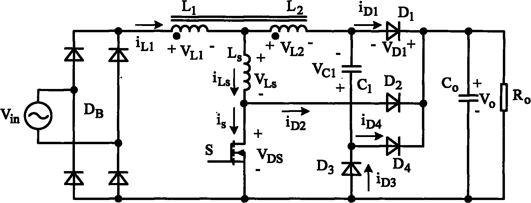
[0012] The inventive circuit such as figure 2 As shown, it includes a diode bridge rectifier circuit and a boost conversion circuit, and the bridge rectifier circuit consists of a rectifier bridge circuit D composed of four diodes B , the boost converter circuit includes an auxiliary coupling winding L with an 2 The boost inductor L 1 , main power switch S, snubber inductor L S , snubber capacitance C 1 , the first diode D 1 , the second diode D 2 , the third diode D 3 , the fourth diode D 4 , the boost inductor L 1 Terminal with the same name and rectifier circuit D B connected to the common cathode terminal, the boost inductor L 1 The non-identical end of the coupling winding L 2 Dotted terminal with snubber inductance L S One end of the snubber inductor L is connected together S The other end of the rectifier circuit D B The main power switch S is connected between the common anode terminals, and the snubber inductor L S The junction with the main power switc...


PUM


Abstract

The invention relates to a power factor correction converter based on a magnetic coupling lossless buffer circuit, comprising a rectifier bridge and a boosted circuit, wherein the boosted circuit comprises a boosted inductor with an auxiliary coupling winding and a buffer network; one end of the boosted inductor is connected with a rectifier bridge common cathode, the other end of the boosted inductor is connected with one end of the coupling winding, and the other end of the coupling winding is connected with a first diode anode; a main switch and a buffer inductor are connected among the boosted inductor, a coupling winding contact and a rectifier bridge common anode, and the buffer inductor and a main switch contact are connected with a second diode anode; a buffer capacitor and a third diode are connected among the coupling winding, a first diode contact and the rectifier bridge common anode, and the buffer capacitor and a third diode cathode contact are connected with a fourth diode anode. The invention can suppress the reverse recovery of the diodes, reduce the switching loss and improve the conversion efficiency; the auxiliary coupling winding is used for resetting the electric current of the buffer inductor; and the buffer capacitor is used for absorbing the energy reversely recovered by the diodes and transmitting the energy into an output capacitor, therefore, the lossless buffering is realized.

Description

technical field [0001] The invention relates to a power factor correction converter, especially a power factor correction converter with a lossless snubber circuit which can reduce diode reverse recovery loss. Background technique [0002] Current single-phase power factor correction converters such as figure 1 As shown, it includes a bridge rectifier circuit DB composed of four diodes, an inductor L, a main power switch S, a diode D and an output capacitor CO. One end of the inductor L is connected to the common cathode end of the rectifier circuit, and the other end is connected to the diode D The anode terminal of the diode D is connected to the anode terminal, the main power switch S is connected between the junction of the inductor L and the diode D and the common anode terminal of the rectifier circuit, the output capacitor CO is connected between the cathode terminal of the diode D and the common anode terminal of the rectifier circuit, and the load RO And connected ...

Claims


Application Information

Patent Timeline
Patent Type & Authority Applications(China)
IPC IPC(8): H02M1/42
CPCY02B70/126Y02B70/10Y02P80/10
Inventor 赵清林杨秋霞张建勇
Owner YANSHAN UNIV
Why Eureka
Try Eureka