Vacuum belt press filter

A vacuum belt type, filter press technology, applied in the direction of filtration separation, moving filter element filter, separation method, etc., can solve the problem of no obvious reduction in moisture content, reduce the vacuum degree of vacuum pressure rollers, etc. The effect of reducing comprehensive cost and high comprehensive treatment benefit

Active Publication Date: 2010-11-17
GUANGXI LIYUANBAO SCI & TECH
View PDF6 Cites 17 Cited by
  • Summary
  • Abstract
  • Description
  • Claims
  • Application Information

AI Technical Summary

Problems solved by technology

However, there are still deficiencies in the above two patents, that is, when the material is squeezed in the filter belt, it will form a trapezoidal filter cake, that is, the middle is thick and the sides are thin. When the vacuum unit connected to the vacuum roller is turned on, a vacuum is formed in the vacuum roller. Under negative pressure, because the material layer on both sides of the filter cake is very thin, it will be sucked through by the vacuum momentarily at first, and a large amount of air will enter the vacuum pressure roller from these two sides, and the vacuum degree in the vacuum pressure roller will be reduced rapidly, so that The thicker part of the filter cake in the middle of the press roller is only subjected to a small negative pressure, or even basically no negative pressure, so it cannot be sucked through at all. Since there is no passage, the moisture in this part of the filter cake is basically not sucked Go, only the moisture in the thin part of the material on both sides is sucked away, so the overall moisture content of the material does not decrease significantly

Method used


Image

  • Vacuum belt press filter
  • Vacuum belt press filter
  • Vacuum belt press filter

Examples


Embodiment Construction

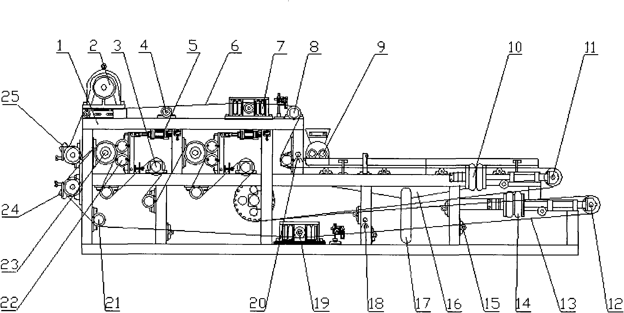
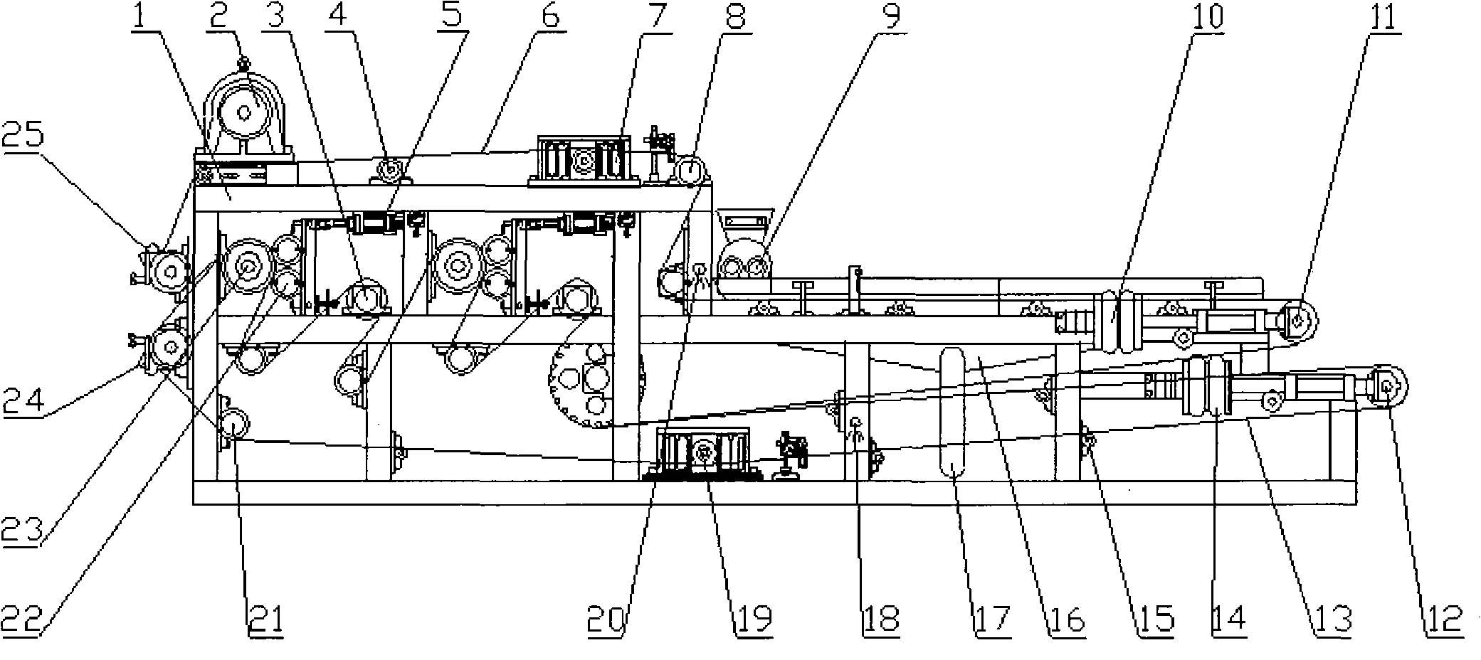
[0030] Such as figure 1 as shown,

[0031] The frame 1 of the vacuum belt filter press of the present invention is equipped with a driving device 2, and the driving device 2 can be a frequency modulation motor, an electromagnetic speed regulating motor, or a diesel (steam) oil machine; it can also be an ordinary motor and various A combination of transmissions or a combination of various speed regulating motors and various transmissions. The filter belt of the filter press is divided into an upper filter belt 6 and a lower filter belt 13. A constant pressure pressure roller 3, an upper filter belt support roller 4, an upper correction device 7, and an upper filter belt guide roller are installed above and below the upper filter belt 6. 8. Upper filter belt tension pneumatic adjustment device 10, upper filter belt tension roller 11, upper filter belt 6 is installed with a feeder 9, and two spiral shafts with opposite feeding directions are installed at the outlet of the feeder...


PUM


Abstract

The invention discloses a vacuum belt press filter, which comprises a frame, a driving device, a feeder, filter belts, a roller, a filter belt tension device, a filter belt cleaning device and a discharger. The driving device is arranged on the frame and drives the roller to rotate and upper and lower filter belts to run. The roller comprises a guide roller, a carrier roller, a constant pressure pressing roller and a vacuum roller. The vacuum belt press filter is characterized in that: the constant pressure pressing roller and/or the vacuum roller performs press filtering on wet materials in a singly mounted or oppositely mounted mode; the vacuum roller is at least provided with two or more vacuum cavities in the same vacuum chamber, and the vacuum cavities are distributed corresponding to the thickness of filter cakes of press-filtering materials, and are distributed from the higher part to the lower part and from the middle part to two sides in turn; during operation, higher and lower vacuum cavities form different vacuum degrees so as to guarantee that all the materials can be penetrated by vacuum negative pressure; and the water which is extruded out of the material surface and adhered on the filter belts is rapidly pumped into a vacuum pressing roller under the action of the mechanical extrusion of the pressing roller. Therefore, the great reduction of the water of press-filtering materials is realized, and the higher comprehensive treatment effect is achieved.

Description

technical field [0001] The invention relates to a solid-liquid separation and dehydration equipment, in particular to a vacuum belt filter press. Background technique [0002] In food, paper, sugar and other industries, it is necessary to filter food, pulp, sucrose juice, etc., while in industrial production such as metallurgy, chemical industry, paper making, leather making, alcohol sewage treatment, poultry breeding, and urban catering waste, it is often necessary to filter The associated waste liquid and waste residue are treated in an environmentally friendly manner, and the first process of waste liquid and waste residue treatment is to perform solid-liquid separation, and after solid-liquid separation, the lower the moisture content of the waste residue, not only from the waste liquid There are more useful substances recovered, and the waste residue is easier to handle, the cost of comprehensive treatment becomes lower, and the economic benefits that can be obtained wi...

Claims


Application Information

Patent Timeline
Patent Type & Authority Applications(China)
IPC IPC(8): B01D33/04
Inventor 邓秀峰邓秀泉邓秀汕
Owner GUANGXI LIYUANBAO SCI & TECH
Why Eureka
Try Eureka