Residual current protector

A technology of residual current and protector, applied in the direction of measuring current/voltage, emergency protection circuit devices, instruments, etc., can solve the problem of excessive size and heat dissipation of power type resistors, affecting the requirements of miniaturization design of products, and on-site use and operation Inconvenience and other problems, to achieve the effect of simplifying the structure, improving safety, reliability and service life, and low cost

Active Publication Date: 2010-11-17
SHANGHAI NOARK ELECTRIC
View PDF7 Cites 21 Cited by
  • Summary
  • Abstract
  • Description
  • Claims
  • Application Information

AI Technical Summary

Problems solved by technology

The biggest disadvantage of using the above two schemes: the power resistance of the test circuit needs to be too large in size and heat dissipation, which not only affects the requirements of product miniaturization design, but more seriously, because the test circuit is installed in any part of the power circuit between the two phases, thus creating reliability and durability issues for the test circuit
However, in the test state, the tripping sensitivity of the existing residual current protector is related to the setting parameters of its tripping sensitivity setter, so it is necessary to set the parameters of the tripping sensitivity setter first during the test operation, and then perform the test. If you do not set it first, the test may fail. You can only adjust the parameters of the trip sensitivity setter after the test is completed, which will bring great inconvenience to the on-site operation.

Method used


Image

  • Residual current protector
  • Residual current protector
  • Residual current protector

Examples


Embodiment Construction

[0028] The nature and advantages of the present invention will become clearer and more comprehensible from the following description of specific embodiments of the invention, given by way of non-limiting examples only and shown in the accompanying drawings.

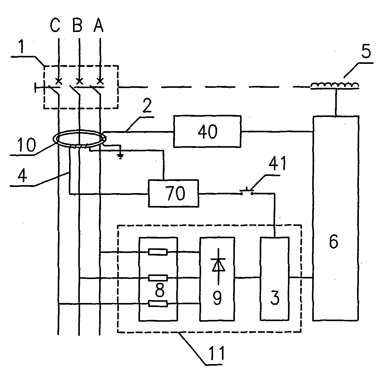
[0029] figure 1 , 5 Middle is a schematic diagram of the overall structure of the residual current protector realized according to the first and second embodiments of the present invention. figure 1 , 5 The circuit breaker body 1 in the circuit breaker is used to connect or break the power lines A, B, and C. The residual current detection device 10 in this embodiment is a zero-sequence current transformer, which can be used to detect residual current or ground fault current. Such as figure 1 The shown residual current detection device 10 includes a ring magnetic core, a primary coil winding and a plurality of secondary coil windings, the primary coil winding is composed of two-phase or multi-phase current conductors, ...


PUM


Abstract

The invention relates to a residual current protector, comprising a zero-sequence transformer, a detection coil, a signal regulation circuit, a logical processing module, a releaser, a test coil and a direct current power supply device. The residual current protector adopts a measurement switch, a simulation current generator, a trip sensitivity setting device and a parameter regulation resistor RS to form a device with optimized performances. A three-jointed RC phase-shifted oscillation circuit is used in the simulation current generator; and the measurement switch controls on-off of a low voltage direct current power supply provided to the RC phase-shifted oscillation circuit, and when the low voltage direct current power supply is switched on, the RC phase-shifted oscillation circuit outputs an excited signal with an alternative current sine wave form to the test coil. The power supply mode of the simulation current generator powered by the low voltage direct current power supply is optimized, and the trip sensitivity of the residual current protector under the test condition is not relevant to the set parameters of the trip sensitivity setting device and is higher than the trip sensitivity of the residual current protector under the normal condition, thereby greatly simplifying the structure of the circuit, reducing the volume of the product and improving the safe reliability and durability of the product.

Description

technical field [0001] The invention relates to an electronic residual current protector with an analog residual current test circuit, in particular to a current operated residual current circuit breaker for judging whether its residual current operating protection function can work normally. Background technique [0002] The residual current protector is a low-voltage electrical appliance commonly used in the power system. The residual current protector is the abbreviation of the residual current action protector, which was previously called the leakage protector. The residual current protector includes a circuit breaker body, a residual current detection device, an electronic logic processing module, a test device and a power circuit. The circuit breaker body includes an operating mechanism, a contact system and a trip unit, which are used to perform the connection or disconnection of the main circuit. Residual current detection device for detection of residual current or...

Claims


Application Information

Patent Timeline
Patent Type & Authority Applications(China)
IPC IPC(8): H02H3/32G01R19/00
Inventor 柴爱军徐泽亮江红高平
Owner SHANGHAI NOARK ELECTRIC
Why Eureka
Try Eureka