
Storage battery charge control circuit adopting two-way reverse connecting protection

A charging control and reverse connection protection technology, applied in battery circuit devices, emergency protection circuit devices, circuit devices, etc., can solve the problems of limited number of contacts, manual replacement, large conduction resistance, etc., to improve work performance and reliability, reduce accidental loss, and improve reliability

Inactive Publication Date: 2010-11-17
HENGYANG ZHONGWEI TECH DEV
View PDF7 Cites 21 Cited by
  • Summary
  • Abstract
  • Description
  • Claims
  • Application Information

AI Technical Summary

Problems solved by technology

[0003] Although it is simple to use a fuse for one-time protection, it is very inconvenient to manually replace a new fuse after the fuse is blown;
[0004] Relay protection is used, the contacts are easy to burn out when working with high current, and the number of contact on and off is limited; diodes, thyristors, transistors, and diodes and field effect transistors are used for series protection, and the on-resistance is large, and the power loss is large when working at high currents. and many more

Method used


Image

  • Storage battery charge control circuit adopting two-way reverse connecting protection
  • Storage battery charge control circuit adopting two-way reverse connecting protection
  • Storage battery charge control circuit adopting two-way reverse connecting protection

Examples


Embodiment 1

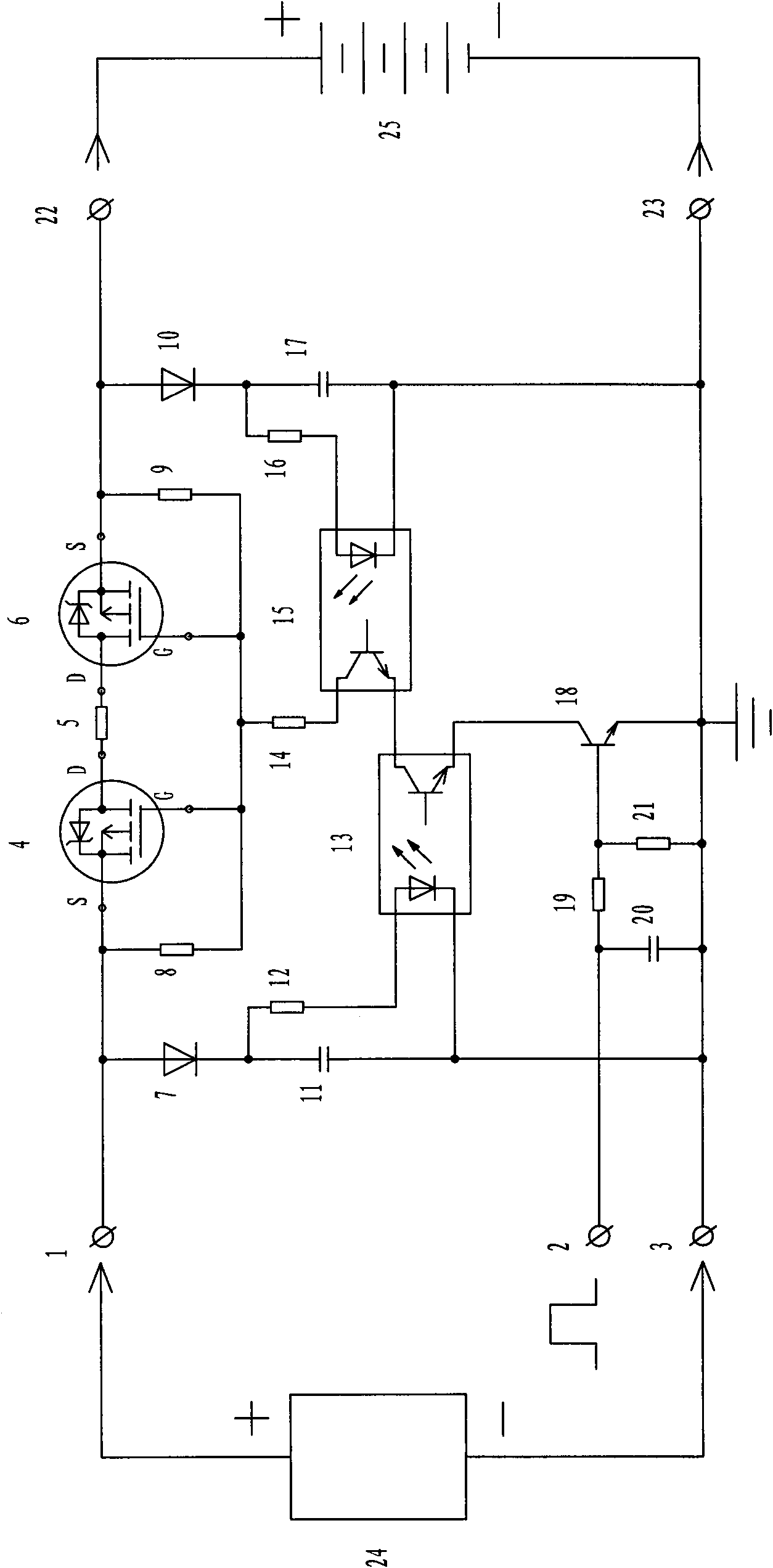
[0032] Embodiment one, as attached figure 1 Shown: a battery charging control circuit using bidirectional reverse connection protection, which is composed of terminal 1, input terminal 2, terminal 3, P-channel field effect transistor 4, resistor 5, P-channel field effect transistor 6, diode 7, and resistor 8 , resistor 9, diode 10, capacitor 11, resistor 12, photocoupler 13, resistor 14, photocoupler 15, resistor 16, capacitor 17, NPN transistor 18, resistor 19, capacitor 20, resistor 21, terminal 22, terminal 23 compositions.

[0033] Terminal 1 is respectively connected with the anode of diode 7, the source (S) of P channel field effect transistor 4, and resistor 8, and the other end of resistor 8 is respectively connected with the grid (G) of P channel field effect transistor 4, resistor 14, P channel The grid (G) of the Doff 6 is connected to the resistor 9, and the other end of the resistance 9 is connected to the source (S) of the P-channel FET 6, the positive pole of t...

Embodiment 2

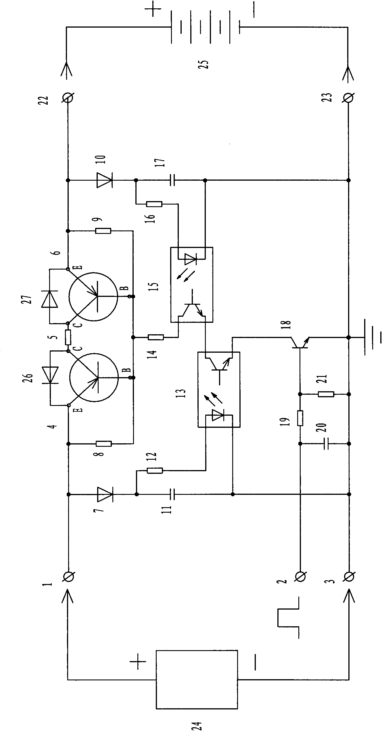
[0034] Embodiment two, as attached figure 2 Shown: a battery charging control circuit using bidirectional reverse connection protection, which is composed of terminal 1, input terminal 2, terminal 3, PNP transistor 4, resistor 5, PNP transistor 6, diode 7, resistor 8, resistor 9, diode 10 , capacitor 11, resistor 12, photocoupler 13, resistor 14, photocoupler 15, resistor 16, capacitor 17, NPN transistor 18, resistor 19, capacitor 20, resistor 21, terminal 22, terminal 23, diode 26, diode 27 compositions.

[0035] Terminal 1 is respectively connected with the emitter (E) of diode 7 anodes, PNP transistor 4, resistor 8, diode 26 cathodes, and the other end of resistor 8 is connected with the base (B) of PNP transistor 4, resistor 14, PNP transistor 6 respectively. The base (B) is connected to the resistor 9, and the other end of the resistor 9 is connected to the emitter (E) of the PNP transistor 6, the negative pole of the diode 27, the positive pole of the diode 10, and the...

Embodiment 3

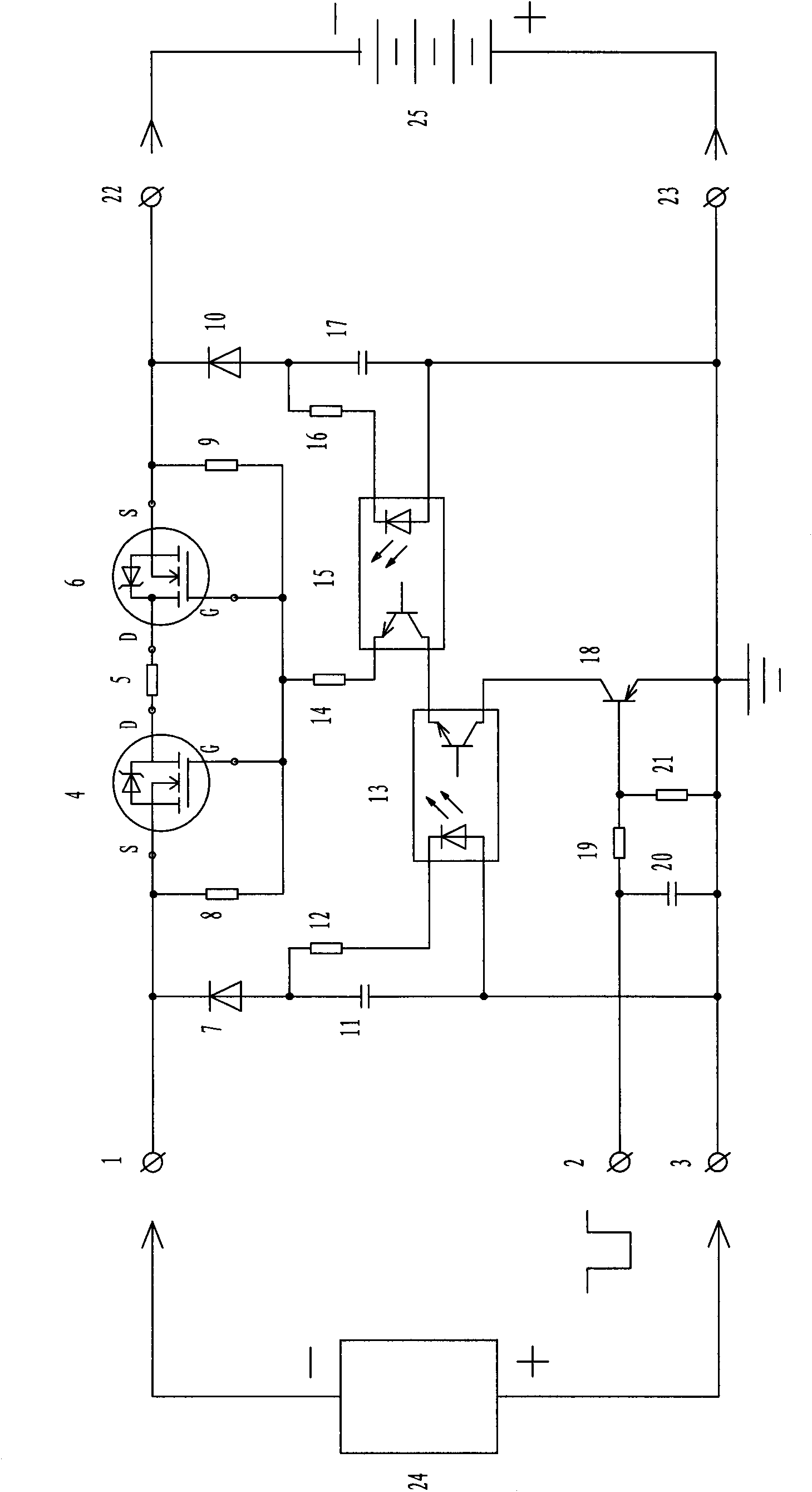
[0036] Embodiment three, as attached image 3 Shown: a battery charging control circuit using bidirectional reverse connection protection, which is composed of terminal 1, input terminal 2, terminal 3, N-channel field effect transistor 4, resistor 5, N-channel field effect transistor 6, diode 7, and resistor 8 , resistor 9, diode 10, capacitor 11, resistor 12, photocoupler 13, resistor 14, photocoupler 15, resistor 16, capacitor 17, PNP transistor 18, resistor 19, capacitor 20, resistor 21, terminal 22, terminal 23 compositions.

[0037] Terminal 1 is respectively connected with the cathode of diode 7, the source (S) of N-channel field effect transistor 4, and resistor 8, and the other end of resistor 8 is respectively connected with the grid (G) of N-channel field effect transistor 4, resistor 14, and N-channel field effect transistor 4. The grid (G) of the Doffet 6 is connected to the resistor 9, and the other end of the resistor 9 is connected to the source (S) of the N-ch...


PUM


Abstract

The invention relates to a storage battery charge control circuit adopting two-way reverse connecting protection, which comprises a terminal 1, an input terminal 2, a terminal 3, a P-channel field-effect transistor 4, a resistor 5, a P-channel field-effect transistor 6, a diode 7, a resistor 8, a resistor 9, a diode 10, a capacitor 11, a resistor 12, a photoelectric coupler 13, a resistor 14, a photoelectric coupler 15, a resistor 16, a capacitor 17, an NPN (Negative-Positive-Negative) crystal triode 18, a resistor 19, a capacitor 20, a resistor 21, a terminal 22 and a terminal 23. By adopting a holohedral symmetry circuit design, the invention can carry out programmable charge on a storage battery while realizing two-way reverse connecting protection on a charge power supply and the storage battery, be effectively applied to various high-power charge devices, such as electric automobiles, other electric vehicles, and the like, be widely applied to various direct current power supply systems so as to ensure that the various direct current power supply systems are effectively protected, improve the reliability of the system and reduce accidental loss caused by improper use, is particularly suitable for carrying out programmable charge and two-way reverse connecting protection on the storage battery in a solar energy and wind energy power supply system and can greatly improve the working performance and the reliability of the solar energy and wind energy power supply system.

Description

technical field [0001] The invention relates to battery charging protection technology, in particular to a battery charging control circuit adopting bidirectional reverse connection protection. Background technique [0002] At present, the adoption of new energy has become an urgent issue facing mankind. When using new energy for power and lighting, it is often necessary to configure a battery power supply system. When using a battery-powered system, no matter whether the charging power supply or the battery is reversed, it will bring serious consequences. In the prior art, fuses, relays, diodes, thyristors, transistors and diodes are generally used in series with field effect transistors to protect the reverse connection of the charging power supply or the reverse connection of the battery. The above methods all have the following disadvantages: [0003] Although it is simple to use a fuse for one-time protection, it is very inconvenient to manually replace a new fuse aft...

Claims


Application Information

Patent Timeline
IPC IPC(8): H02J7/00H02H7/18H02H11/00
Inventor 胡旻宇胡海洋
Owner HENGYANG ZHONGWEI TECH DEV
Features
  • Generate Ideas
  • Intellectual Property
  • Life Sciences
  • Materials
  • Tech Scout
  • Unparalleled Data Quality
  • Higher Quality Content
  • 60% Fewer Hallucinations
Learn More