Scrap steel pre-heating conveyor with short process

A conveying device and short process technology, applied in the field of metallurgy, can solve the problems of increasing equipment wear, increasing the transmission power of the mechanism, etc., and achieve the effects of small equipment vibration, simple maintenance and production, and improved service life.

Inactive Publication Date: 2010-12-08
CISDI ENG CO LTD
View PDF7 Cites 17 Cited by
  • Summary
  • Abstract
  • Description
  • Claims
  • Application Information

AI Technical Summary

Problems solved by technology

In fact, consteel is horizontally conveyed, and the movement of scrap steel must overcome the friction force during the reciprocating movement of scrap steel in the groove, which increases the transmission power of the mechanism on the one hand, and increases the wear and tear of the equipment on the other hand

Method used


Image

  • Scrap steel pre-heating conveyor with short process
  • Scrap steel pre-heating conveyor with short process
  • Scrap steel pre-heating conveyor with short process

Examples


Embodiment 1

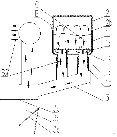
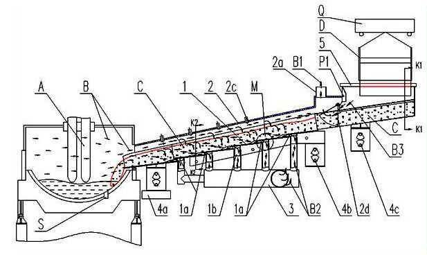
[0038] Example 1 as figure 1 As shown, the conveying trough 1 is installed obliquely, and the lower end extends into the electric furnace A. The conveying trough is covered with a smoke guide 2. The movement gap between the two is kept sealed by the first dynamic sealing device 2b to prevent cold air from being sucked in. The smoke guide 2 There is a regulating smoke port 2a at the tail of the furnace; the flue gas B fills the entire electric furnace A and the cavity channel formed by the scrap steel preheating conveying chute 1 and the smoke hood 2. Structure, every two-layer junction gap is designed as the smoke outlet 1a at the bottom of the tank, the bottom layer is connected with the bottom exhaust pipe 1b, and the entire scrap steel preheating conveying chute can be provided with several smoke outlets 1a at the bottom of the tank. Steel scrap C is hoisted into several bottom-opening long distributing troughs D by disks in the stockyard, and a bottom-opening long distribu...

Embodiment 2

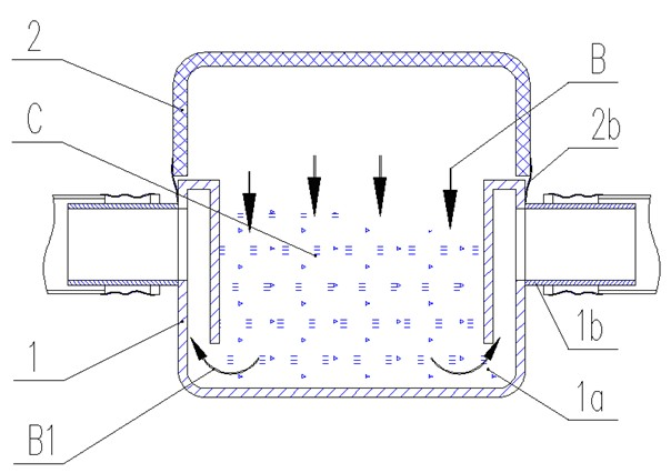
[0045] Embodiment 2: what is different from Embodiment 1 is the structure of the delivery trough, such as Figure 5 As shown, the inclined conveying trough 1 adopts the embodiment of suction on both sides, the two side walls are double-layered, and the inner side wall is separated from the bottom of the tank to form a side-inclined smoking port 1a.

[0046] It should be pointed out that the above-mentioned conveying trough 1, smoke guide 2 and other related parts that are in contact with the high-temperature flue gas B can be made into a water-cooled structure to withstand high temperatures, and some components can also be coated with heat-insulating and refractory materials to increase the life of the components and reduce the Reduce the temperature loss of the exhaust gas and improve the thermal efficiency of the subsequent system.

[0047] It is also necessary to set some sensors on this device to cooperate with the production process and improve the working conditions of t...


PUM


Abstract

The invention discloses a scrap steel pre-heating conveyor with a short process, comprising a conveying trough (1) which is provided with a fume guiding hood (2) and is inclined relative to the horizontal plane. The lower end of the conveying trough (1) extends into an electric furnace (A) via an opening on the sidewall of the electric furnace (A); a bottom-opened long distributing trough (D) is arranged above the other end of the conveying trough (1), is arranged above a material receiving section of the conveying trough (1) by a swing device (Q), and is arranged in the downward projection of the material receiving section of the conveying trough (1) longitudinally; and scrap steels (C) are longitudinally arranged at the bottom of the material receiving section of the conveying trough (1) in a strip shape, and then the conveying trough (1) conveys the scrap steels (C) into the electric furnace (A). The scrap steel pre-heating conveyor with a short process is short, has high heat exchange efficiency, low operation rate of a crane, small abrasion, less maintenance, energy conservation, environment protection and reduces investment and operation cost, thus the invention is a new energy-saving and environment-friendly technology with promotional value in smelting technique, such as electric furnaces and the like.

Description

technical field [0001] The invention belongs to the technical field of metallurgy and relates to a short-flow electric furnace scrap preheating and continuous feeding device. Background technique [0002] Energy saving, consumption reduction, and environmental protection in electric furnace steelmaking have always been one of the core technologies in the development of global electric furnace steelmaking technology. There have been many design schemes at home and abroad in the past 20 years, but due to its technical difficulty, only a small amount of technology has been put into practical use at present. Its typical representative is the CONSTEEL (US Patent No. US5400358) technology based on continuous vibration feeding. This is a This kind of horizontal continuous feeding technology can realize stable arc smelting in electric furnace, which is environmentally friendly and reduces electrode consumption, which can greatly reduce the production process cost of electric furnac...

Claims


Application Information

Patent Timeline
Patent Type & Authority Applications(China)
IPC IPC(8): F27D3/00F27D13/00
Inventor 黄其明杨宁川廖远刘春霆刘向东
Owner CISDI ENG CO LTD
Why Eureka
Try Eureka