Method for integrating power equipment state monitoring devices

A technology of state monitoring device and integration method, which is applied in the field of monitoring, can solve problems such as the inability to share state monitoring information, the small amount of information released, and poor system interoperability, and achieve the effect of meeting the needs of panoramic state information monitoring

Active Publication Date: 2010-12-15
河北卫讯电力自动化设备有限公司
View PDF5 Cites 34 Cited by
  • Summary
  • Abstract
  • Description
  • Claims
  • Application Information

AI Technical Summary

Problems solved by technology

[0003] 1) Status monitoring information cannot be shared
The condition monitoring system is still in the decentralized monitoring stage and is independent of the computer monitoring system. Between the power control center and each substation, and between the condition monitoring system and other systems, the data information model and communication interface are highly heterogeneous, making it difficult to make full use of different Information for condition assessment, fault diagnosis and condition maintenance of equipment
[0004] 2) Poor interoperability between condition monitoring devices
[0008] 2) Adopting a character mark-oriented transmission protocol, mainly considering the unification of the data format of the specific equipment, the data transmission efficiency is not high, the usability is not strong, and the amount of information release is small
[0009] 3) It is not only necessary to consider the maintenance of network connections, but also to define each layer of data packets in detail, and must also deal with specific message formats, high and low bytes, etc., and its scalability and readability are poor
[0010] 4) The point-oriented data description method is adopted, and various actual devices are not modeled and described, resulting in poor interoperability between different systems
[0013] 1) IEC 61850 is a huge technical system, and it does not stay at the level of communication protocols, nor does it define specific implementation details
In addition, as the technical system of the substation internal communication network, IEC

Method used


Image

  • Method for integrating power equipment state monitoring devices
  • Method for integrating power equipment state monitoring devices
  • Method for integrating power equipment state monitoring devices

Examples


Embodiment Construction

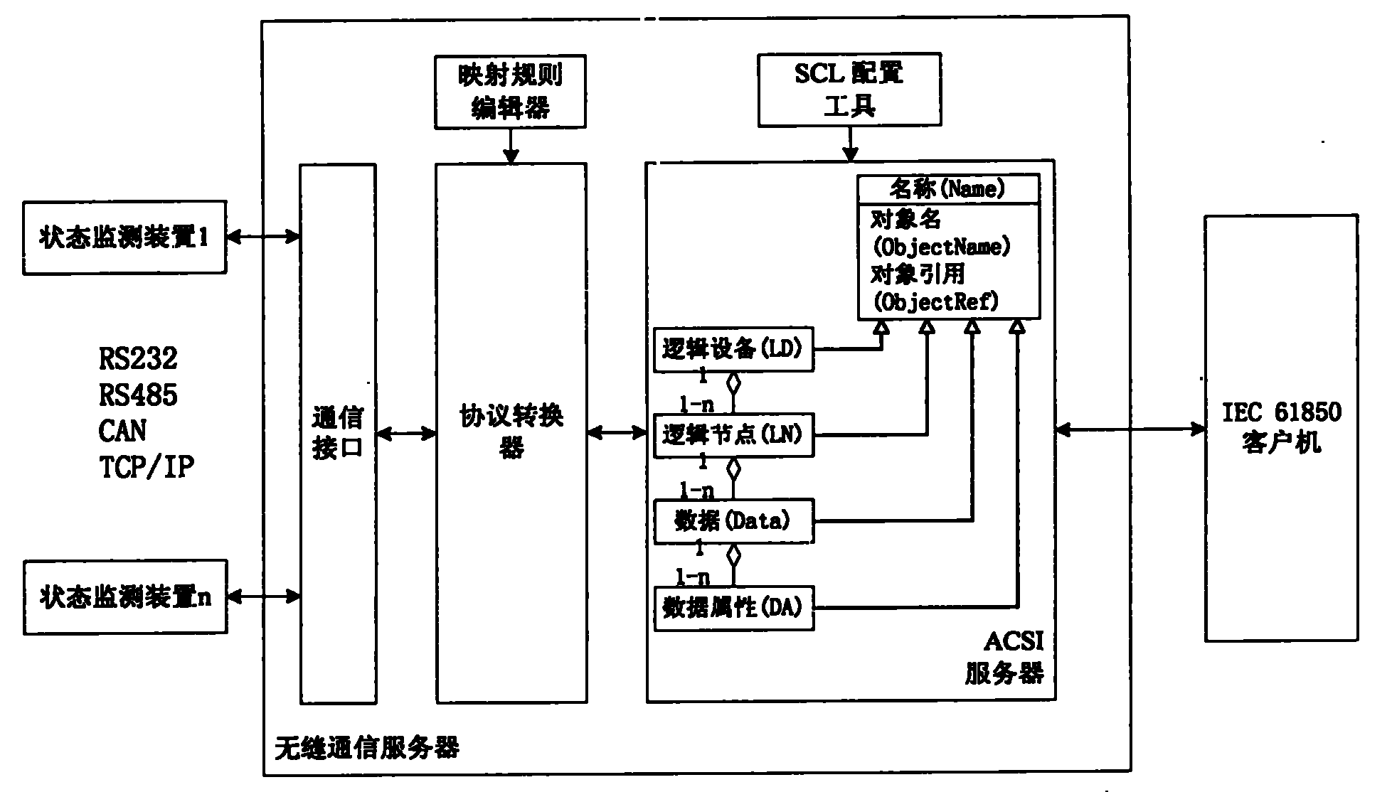
[0036] see figure 1 , the seamless communication server is the core of the present invention, and mainly includes modules such as communication interface, mapping rule editor, protocol converter, SCL configuration tool and ACSI server, and the functions of each part are as follows:

[0037] 1) Communication interface

[0038] Provide RS232, RS485, CAN bus or TCP / IP interface, access to different manufacturers, different communication interfaces, non-IEC 61850 communication protocol condition monitoring devices or systems, such as capacitive equipment, lightning arresters, transformer oil chromatography and partial discharge in substations , circuit breakers and other on-line monitoring devices, pollution and icing on-line monitoring systems in the form of GSM text messages, video and image on-line monitoring systems in the form of GPRS / CDMA, and insulator on-line monitoring systems in the form of wireless sensor networks, etc., and the collected status Data is loaded into the...


PUM


Abstract

The invention discloses a method for integrating a power equipment state monitoring device. The technical scheme is that: a seamless communication server consists of a communication interface, a protocol converter and an ACSI server, and an IEC 61850 client is directly connected with the ACSI server; and transmission and transformation state online monitoring devices in different types are accessed through the provided communication interface. In the method, a mapping rule is established between a traditional protocol and the IEC 61850 by a mapping rule editor; the protocol converter finishes protocol conversion between the traditional protocol and the IEC 61850 by using the mapping rule so as to realize the communication between different transmission and transformation state online monitoring devices and the ACSI server to realize communication between the different transmission and transformation state online monitoring devices and the IEC 61850 client. The method for integrating the power equipment state monitoring devices radically solves the problem that the conventional power grid state online monitoring devices are difficult for interoperation and information sharing, and can better meet the requirements of an intelligent power grid on panoramic state information monitoring.

Description

technical field [0001] The invention relates to an integration method of a state monitoring device of electric power equipment, which can realize interoperability and information sharing among state monitoring devices of different manufacturers under the IEC 61850 technical system, and belongs to the field of monitoring technology. Background technique [0002] The investigation of catastrophic blackout accidents in domestic and foreign power grids shows that although there are advanced control systems and advanced operation application software, the aging transmission grid and outdated power transmission and transformation equipment have caused the power grid to work in a dangerous area. The failure of power transmission and transformation equipment itself has always been one of the main reasons that endanger the safe operation of the power grid, and it also accounts for a considerable proportion of the causes of power grid failures. Domestic and foreign power grid conditio...

Claims


Application Information

Patent Timeline
IPC IPC(8): H02J13/00
CPCY02E60/723Y04S10/16Y02E60/00
Inventor 王德文朱永利邸剑翟学明张长明宋亚奇阎蕾王艳
Owner 河北卫讯电力自动化设备有限公司
Why Eureka
Try Eureka