
Permanently-magnetic synchronous heat-stretching roller motor

A technology of permanent magnet synchronization and hot drawing, applied in synchronous machines, electrical components, electromechanical devices, etc., can solve the problems of reduced cooling effect, short axial dimension, shortened service life, etc., and achieve low insulation aging and heat insulation The effect of extending the distance and prolonging the service life

Inactive Publication Date: 2010-12-15
ZHEJIANG LANXIANG ELECTROMECHANICAL EQUIP MFG
View PDF6 Cites 3 Cited by
  • Summary
  • Abstract
  • Description
  • Claims
  • Application Information

AI Technical Summary

Problems solved by technology

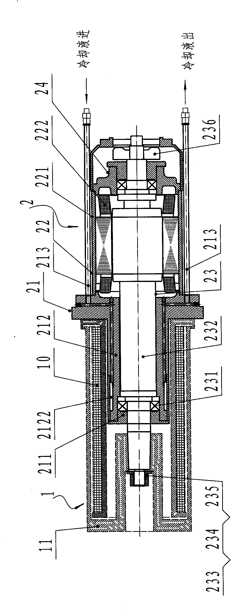
[0005] 1. Since the axial dimension of the annular groove 2122 is short, its design structure only plays a single role of cooling the front bearing 231;
[0006] 2. The setting of the annular groove 2122 makes the front end cover 212 corresponding to the front bearing 231 form a thin-walled structure, so that the strength of the front end cover 212 is greatly reduced, and the noise and vibration of the motor assembly 2 increase when it runs at high speed. poor reliability;
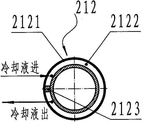
[0007] 3. The coolant inlet and outlet of the annular groove 2122 are only separated by the spacer 2123, which cannot form a completely smooth coolant inlet and outlet circuit. During the cooling process, the cold and heat exchange cannot be fully and completely performed, and the front end cover 212 is cooled. uneven temperature
Due to the thin wall thickness of the sealing cylinder 2121, the uneven cooling temperature will easily cause deformation of the thin-walled welding piece structure sealing cylinder 2121, which will cause leakage of coolant at the welding seam, damage the heater insulation of the roller body 1, and in severe cases The cooling liquid will also flow out of the surface of the godet 11, contaminate the spindles, and cause batches of drawn wires to be scrapped; at the same time, the pressure difference between the cold and hot cooling liquids weakens the flow rate of the cooling liquid and reduces the cooling effect;
[0008] 4. With the continuous development of spinning technology, the heating temperature of the roller body 1 during spinning operation is as high as 250°C, and the motor speed of the hot drawing roller has reached 5500r / min~8000r / min. Under high temperature and high speed working conditions, Because the roller body 1 is longer and the axial dimension of the annular groove 2122 is shorter, the front end cover 21 bears the heat radiation of the heater 10 and conducts the heat to the frame 221, while the temperature inside the motor assembly 2 itself is already low. Higher, which makes the heat dissipation of the motor assembly 2 by the tail fan 236 arranged on the rotor assembly 23 alone, the effect is not very ideal, and the temperature of the whole machine of the motor assembly 2 increases, which accelerates the heat dissipation in the iron core 222 with windings. The insulation is aging, and the failure rate of the motor assembly 2 is high, which greatly shortens its service life

Method used


Image

  • Permanently-magnetic synchronous heat-stretching roller motor
  • Permanently-magnetic synchronous heat-stretching roller motor
  • Permanently-magnetic synchronous heat-stretching roller motor

Examples


Embodiment Construction

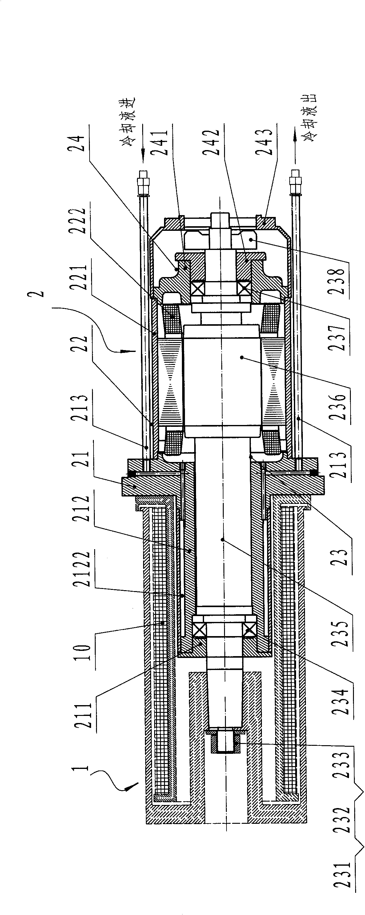
[0023] see Figure 3 ~ Figure 5 Shown is a preferred embodiment of the present invention.

[0024] A permanent magnet synchronous thermal drafting roller motor is composed of a hollow roller body 1 and a motor assembly 2. The motor assembly 2 is composed of a rear end cover 24, a stator assembly 22, a rotor assembly 23 and a front end cover 21. The rear end cover 24 is composed of a rear end cover 241, a rear gland 242 and a windshield 243. The stator assembly 22 is press-fitted together by a machine base 221 and a winding core 222. The rear end cover 241 is fixedly connected to the machine base 221. The front end cover The part 21 is composed of a front gland 211, a front end cover 212 and an inlet and outlet coolant pipe 213 located on the machine base 221. The front end cover 212 is a cylindrical structure extending in the roller body part 1, and its bottom end surface is fixedly connected with the machine base 221. And its far-end surface is fixedly connected with the fro...


PUM


Abstract

The invention discloses a permanently-magnetic synchronous heat-stretching roller motor, which can be used for a textile yarn and industrial yarn spinning and stretching combination machine. The motor consists of a hollow roller body part and a motor assembly, wherein the motor assembly consists of a back end cover part, a stator component, a rotor component and a front end cover part; the front end cover part consists of a front gland, a front end cover and an inlet and outlet cooling liquid pipe arranged on an engine base; the front end cover has a cylindrical structure extending into the roller body part; a heater is arranged in the roller body part along the axial length of the roller body part and fixed on the bottom end face of the front end cover; the inlet and outlet cooling liquid pipe is communicated with a cooling passage formed on the front end cover and is externally connected with a cooling loop; the cooling passage has an S-shaped end-to-end connected structure uniformly formed at the outer edge of the front end cover; a sealing barrel is packaged on the surface of the outer edge; and the axial length of the cooling passage is close to that of the front end cover. Due to the adoption of the technical scheme, the motor has the advantages of good cooling effect under a high-temperature and high-speed working environment, small temperature rise and long service life.

Description

【Technical field】 [0001] The invention relates to a permanent magnet synchronous thermal drawing roller motor, which can be used in civil chemical fiber yarn and industrial chemical fiber yarn spinning and pulling machines. 【Background technique】 [0002] In the spinning and fiber combined spinning machine, the hot draft roller and the split roller are the key components. The chemical fiber spinning is realized through the hot draft roller and the split roller. The hot draft roller motor and the split roller motor are respectively Power source for heat roll and split roll. [0003] figure 1 It is a typical structure schematic diagram of a commonly used hot drawing roller motor, figure 2 It is a schematic diagram of the structure of the front end cover including the envelope. The motor assembly 2 is composed of a front end cover part 21 , a stator assembly 22 , a rotor assembly 23 and a rear end cover part 24 . The stator assembly 22 is composed of a frame 221 and a wind...

Claims


Application Information

Patent Timeline
Patent Type & Authority Applications(China)
IPC IPC(8): H02K21/00H02K9/19H02K9/06
Inventor 任发翔李建文汪岳见顾美华
Owner ZHEJIANG LANXIANG ELECTROMECHANICAL EQUIP MFG
Learn More