Method for calibrating distance between scan lines of scanning electron microscope by utilizing moires

A scanning electron microscope and scanning line technology, applied in the field of photomechanics, can solve the problems of inability to meet high-precision measurement, not considering working distance, measurement accuracy changes, etc., and achieve the effects of high precision, real-time in-situ calibration, and high measurement sensitivity

Inactive Publication Date: 2010-12-22
TSINGHUA UNIV
View PDF4 Cites 10 Cited by
  • Summary
  • Abstract
  • Description
  • Claims
  • Application Information

AI Technical Summary

Problems solved by technology

At present, most scanning electron microscopes are only calibrated by the manufacturer's engineers according to the grid or other samples provided by the manufacturer when the instrument leaves the factory or when the instrument is accepted. Therefore, the calibration accuracy is low. When measuring the length of an object, the general and accurate value There are different degrees of deviation between them, which cannot meet the requirements of high-precision measurement such as micro-nano scale measurement
In addition, the measurement accuracy will also change with the change of working distance and other factors, while the traditional calibration method does not consider the influence of working distance

Method used


Image

  • Method for calibrating distance between scan lines of scanning electron microscope by utilizing moires
  • Method for calibrating distance between scan lines of scanning electron microscope by utilizing moires
  • Method for calibrating distance between scan lines of scanning electron microscope by utilizing moires

Examples


Embodiment 1

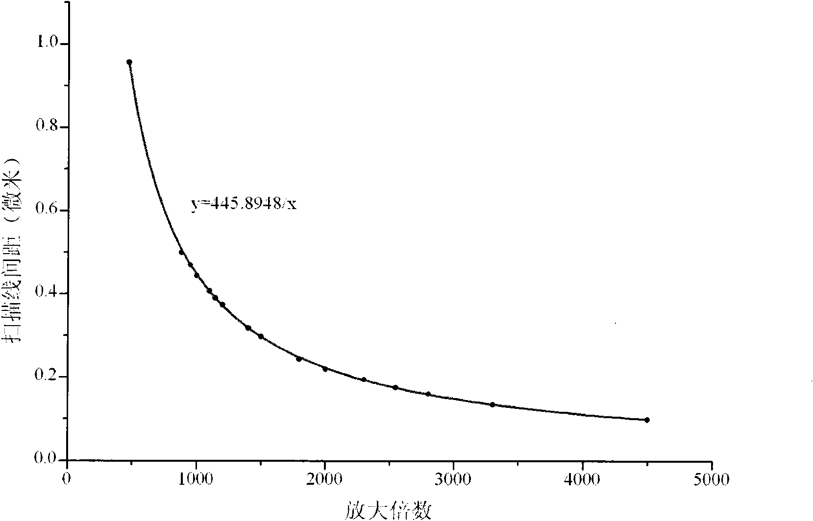
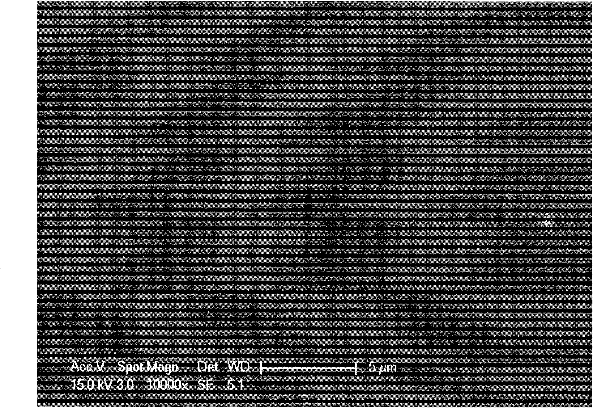
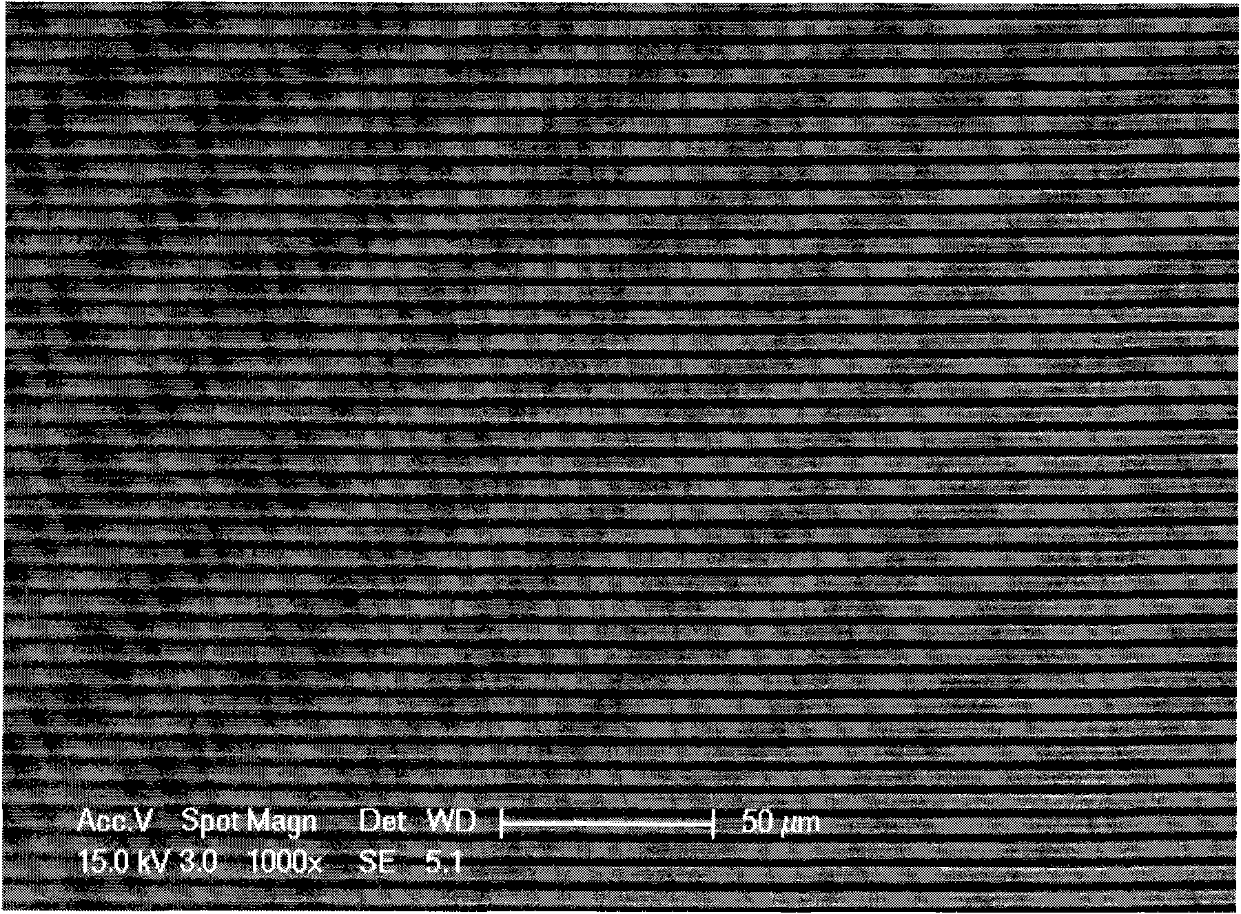
[0027] The scanning electron microscope model used is FEI Sirion 400NC. Firstly, perform a preliminary calibration of the scanning line spacing of the scanning electron microscope: take a calibration specimen and place it on the scanning electron microscope sample stage, select the number of scanning lines and working distance: 484 lines and 5.1mm, and record the images and images of the specimens at different magnifications Ruler, use image software such as Photoshop to measure the number of pixels corresponding to the image ruler at different magnifications, obtain the calibrated physical size corresponding to each pixel, that is, the scan line spacing, and fit the scan line spacing and the magnification to get the fit Curve and its expression, such as figure 1 Shown. The standard grating used in this experiment is a parallel grating of 2000 lines / mm, then when the scanning line pitch is equal to the standard grating pitch, zero field moiré is formed. According to the fitting...


PUM


Abstract

The invention relates to a method for calibrating distance between scan lines of a scanning electron microscope by utilizing moires, which belongs to the technical field of photomechanics. The method comprises the following steps: by using the scan lines of the scanning electron microscope as a reference grating and using the standard grating of a given grating pitch as a specimen grating, enabling the two gratings to generate interference so as to form clear parallel moires, measuring the pixel distance of the moires, and substituting the pixel distance in a deduced inversion formula to calculate the actual physical dimension corresponding to each pixel, thereby obtaining the distance between the scan lines. The method integrates the advantages of high measuring sensitivity, large viewing field and the like in the moire method, can realize real-time in-situ calibration, has the characteristics of high accuracy and simple operation, considers the influences of a plurality of factors, such as the number of scan lines, working distance and the like, and provides favorable foundation for the scanning electron microscope and the scanning electron microscope moire method to be used in measuring micro / nano deformation.

Description

Technical field [0001] A method for calibrating the scanning line spacing of a scanning electron microscope by using moiré belongs to the technical field of photometric mechanics. Background technique [0002] Scanning electron microscopy, as a means of observation and analysis of small-scale samples, is widely used in chemistry, biology, medicine, and metallurgy due to its simple sample preparation, wide range of adjustable magnification, high image resolution, and large depth of field. , Materials, semiconductor manufacturing and microcircuit inspection and other fields. At present, most scanning electron microscopes are only simply calibrated by the manufacturer’s engineers according to the grid or other samples provided by the manufacturer when the instrument is shipped or accepted. Therefore, the calibration accuracy is low. When measuring the length of the object, it is generally and accurate. There are different degrees of deviation between them, which cannot meet the req...

Claims


Application Information

Patent Timeline
IPC IPC(8): G01B7/02G01B7/16
Inventor 谢惠民李艳杰王怀喜唐敏锦
Owner TSINGHUA UNIV
Why Eureka
Try Eureka