
Distribution valve and mud or concrete pump with same

A technology for distributing valves and mud, which is applied to parts, pumps, and pump components of pumping devices for elastic fluids, and can solve problems such as large crushing force, inability to use one pump for multiple purposes or one valve for multiple purposes, and affect progress. Good sealing performance, improving the effect of not easy to segregate and improving efficiency

Active Publication Date: 2010-12-29
海宁经开产业园区开发建设有限公司
View PDF6 Cites 3 Cited by
  • Summary
  • Abstract
  • Description
  • Claims
  • Application Information

AI Technical Summary

Problems solved by technology

[0007] 1. The manufacturing process of the valve body is complicated, and the resistance, wear, vibration, and crushing force are greater when used, and the power consumption is greater;
[0008] 2. The function is single, one pump cannot be used for multiple purposes or one valve can be used for multiple purposes, and there is dependence on feeding;
[0009] 3. The feeding method is an open hopper, feeding and feeding by external power, which consumes energy;
[0010] 4. The core of the disadvantages of the two valves is that they are not sealed, they cannot be self-priming, and they are easy to enter air. They are easy to fire during the process of conveying materials, and it is easy to cause the volume of the clay cylinder to be unsaturated;
[0011] 5. Especially when transporting downhill, it is more difficult, sand and gravel separation, mud and water separation, easy to segregate, easy to block the pipe, affect the progress, and the volume is large and expensive

Method used


Image

  • Distribution valve and mud or concrete pump with same
  • Distribution valve and mud or concrete pump with same
  • Distribution valve and mud or concrete pump with same

Examples


Embodiment 1

[0048] Example 1: Single cylinder mud or concrete pump with one valve cylinder

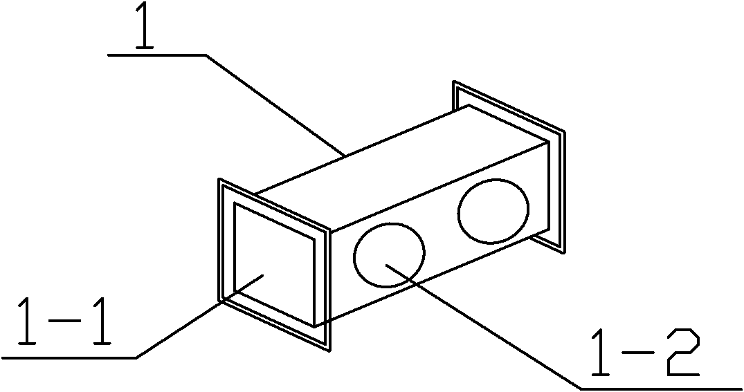
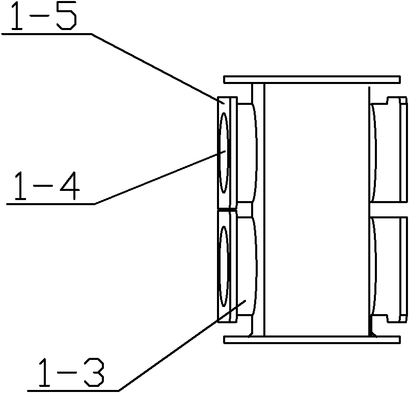
[0049] Such as image 3 , Figure 4-a and Figure 9 As shown, the mud cylinder 5 communicates with the two round pipes 1-3 of the distribution valve 1 through the V-shaped pipe 6, and the two round pipes 1-3 on the other side communicate with the straight pipe 7 respectively. The valve oil cylinder 9 is arranged above the valve block 1, the piston connecting rod 10 runs through the valve oil cylinder 9, and its two ends are connected with the plunger rod 8-2, and the middle part of the piston connecting rod 10 is fixed to make it move left and right in the valve oil cylinder 9. The piston 10 - 1 ; the piston connecting rod 10 is fixed to the valve block 1 through the bearing bracket 11 , and the bearing bracket 11 is fixed on the valve block 1 .

[0050] Working process of the present invention:

[0051] The pump production process uses a 32-horsepower diesel engine as the power source to driv...

Embodiment 2

[0053] Example 2: Single cylinder mud or concrete pump with two valve cylinders

[0054] Such as image 3 , Figure 4-b and Figure 9 As shown, the mud cylinder 5 communicates with the two round pipes 1-3 of the distribution valve 1 through the V-shaped pipe 6, and the two round pipes 1-3 on the other side communicate with the straight pipe 7 respectively. There is one valve oil cylinder on the left side and one right side of the valve block, and the plunger rod 8-2 extends into the valve oil cylinder 9; a shock absorber is arranged between the valve oil cylinder 9 and the column chamber 8, and the piston end of the plunger rod 8-2 is equipped with There is a buffer device.

[0055] Working process of the present invention:

[0056] First, the solenoid valve in the hydraulic station closes the output hole of the hydraulic station I# and opens the output hole of the hydraulic station II#, and sends the pressure oil of the hydraulic station to the accumulator, and then the a...

Embodiment 3

[0057] Example 3: Twin Cylinder Slurry or Concrete Pump with Two Valve Cylinders

[0058] Such as Figure 5 , Figure 6-a and Figure 9 As shown, the main oil cylinder 2, the piston rod 3, and the mud cylinder 5 each have two and are arranged in parallel. The two main oil cylinders 2 are connected to the mud cylinder 5 through the washing pool 4. Into, the tail ends of the two main oil cylinders 2 are connected in series. The mud cylinder 5-1 communicates with the two right circular pipes 1-3-1 in the vertical direction of the distribution valve through the V-shaped pipe 6, and the mud cylinder 5-2 communicates with the two left circular pipes in the vertical direction of the distribution valve through the V-shaped pipe 6. The tubes 1-3-2 are connected, and the two circular tubes 1-3-1 and 1-3-2 in the horizontal direction of the corresponding surface are respectively connected with the Y-shaped tube. The valve cylinder 9 is arranged above and below the valve block 1, the ...


PUM


Abstract

The invention discloses a distribution valve and a mud or concrete pump with the same. The distribution valve comprises a valve block, a valve oil cylinder and a column compartment, the valve block is internally and transversely provided with a square section channel; two surfaces perpendicular to the square-shaped section channel are both provided with two circular holes communicated with the square-shaped section channel; circular tubes with flanges extends outwards from the circular holes; the circular tubes are internally provided with sleeves; the square-shaped section channel of the valve block is communicated with the column compartment of a uniform section; the column compartment is internally provided with a rectangular-column plunger; the outer end of the rectangular-column plunger is provided with a plunger rod; and the valve oil cylinder is arranged outside the valve block. A main oil cylinder of the mud or concrete pump is connected with a mud cylinder through a wash trough; a sensor is arranged above the wash trough; and the mud cylinder is communicated with the two circular tubes of the distribution valve through a V-shape tube. The invention adequately reflects theadvantages of multi-functions of the distribution valve and the mud or concrete pump. The mud or concrete pump is not only a self-suction type mud pump, but also a medium-pressure concrete pump; and in addition, the distribution valve can be used for a transmission part and can be used as a compensating cylinder.

Description

technical field [0001] The invention relates to a fluid conveying machine, in particular to a distributing valve and a mud or concrete pump with the distributing valve. Background technique [0002] For the water conservancy department on the agricultural front, the era of vigorous farmland capital construction in the 1960s has passed. Due to years of disrepair, farmland water conservancy drainage and irrigation facilities are in urgent need of dredging. At present, there is only one kind of mud pump, and the maximum mud content for removing silt is only 25 %, it will cause floods and disasters when used, and it is difficult to meet the requirements now. [0003] After the implementation of the annual production responsibility system in the countryside in 1978, farmers dug fish ponds in low-lying land, which has been silted up for many years and is in urgent need of dredging. The current method: wait until winter to ditch the fish ponds to improve water use, and then dig th...

Claims


Application Information

Patent Timeline
IPC IPC(8): F04B53/12F04B15/02
Inventor 邵启栋
Owner 海宁经开产业园区开发建设有限公司
Learn More