
MOS (Metal Oxide Semiconductor) transistor and manufacture method thereof

A technology of MOS transistors and manufacturing methods, which is applied in the field of MOS transistors and their manufacturing, can solve the problems of unsatisfactory process development requirements, single structure of MOS transistors, and inflexible design, and achieve flexible layout, reduced volume, and improved utilization. Effect

Inactive Publication Date: 2010-12-29
SEMICON MFG INT (SHANGHAI) CORP
View PDF1 Cites 4 Cited by
  • Summary
  • Abstract
  • Description
  • Claims
  • Application Information

AI Technical Summary

Problems solved by technology

[0006] The structure of the MOS transistor formed by the existing technology is single, and the design is not flexible enough; and as the integration of semiconductor devices becomes higher and higher, the room for its volume to become smaller becomes smaller and smaller, which cannot meet the needs of process development

Method used


Image

  • MOS (Metal Oxide Semiconductor) transistor and manufacture method thereof
  • MOS (Metal Oxide Semiconductor) transistor and manufacture method thereof
  • MOS (Metal Oxide Semiconductor) transistor and manufacture method thereof

Examples


Embodiment Construction

[0029] The purpose of the present invention is to further reduce the volume of MOS transistors, meet the trend of increasing integration of semiconductor devices, improve the utilization rate of chip area, and make the layout more flexible. In addition, the corners of the first n-type polysilicon layer and the second n-type polysilicon layer are subjected to high-temperature treatment to make them smooth, so as to solve the corner effect caused by the strong current at the corners of square corners.

[0030] The specific implementation method of forming a MOS transistor in the present invention includes: sequentially forming an oxide layer, a first p-type polysilicon layer, a first n-type polysilicon layer, a second p-type polysilicon layer and a second n-type polysilicon layer on a semiconductor substrate; Etching the second n-type polysilicon layer, the second p-type polysilicon layer, the first n-type polysilicon layer and the first p-type polysilicon layer to define source / ...


PUM

PropertyMeasurementUnit
Thicknessaaaaaaaaaa
Thicknessaaaaaaaaaa

Abstract

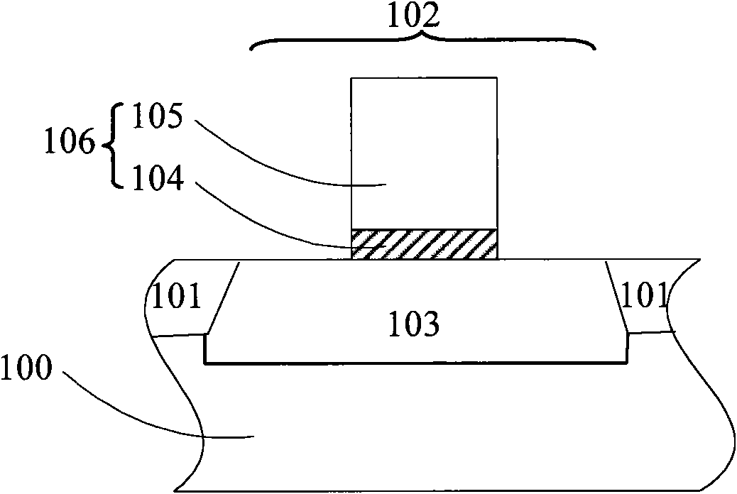
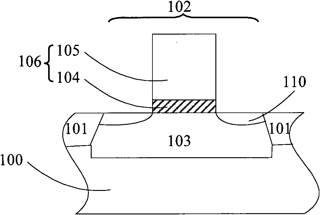
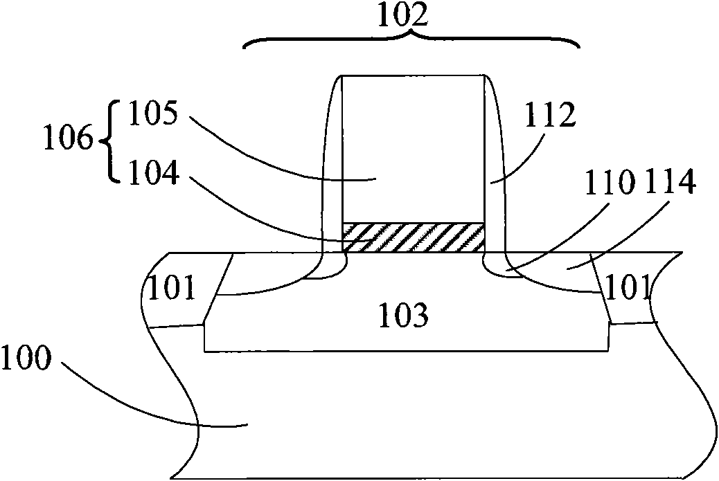
The invention relates to an MOS (Metal Oxide Semiconductor) transistor and a manufacture method thereof, wherein the MOS transistor comprises a semiconductor substrate, a first grid through hole, a second grid through hole, grid dielectric layers, grids, source / drain extension regions and side walls, wherein the semiconductor substrate sequentially comprises an oxidization layer, a first p-type polysilicon layer, a first n-type polysilicon layer, a second p-type polysilicon layer and a second n-type polysilicon layer; the first grid through hole is positioned in the first p-type polysilicon layer; the second grid through hole is positioned in the second p-type polysilicon layer; the grid dielectric layers are positioned on the second n-type polysilicon layer and the inner walls of the first grid through hole and the second grid through hole; the grids are positioned on the gird dielectric layers and in the first grid through hole and the second grid through hole; the source / drain extension regions are positioned in source / drain regions at two sides of the grids; the side walls are positioned at two sides of the grids and the two sides of the source / drain regions; wherein the first n-type polysilicon layer and the second n-type polysilicon layer have smooth corners after processed at high temperature. The invention improves the utilization ratio of the chip area, and solves the corner effect caused by strong corner current.

Description

technical field [0001] The invention relates to the technical field of semiconductors, in particular to a MOS transistor and a manufacturing method thereof. Background technique [0002] As the semiconductor industry develops towards smaller and faster devices, the feature lateral dimensions and depths of semiconductor devices are gradually reduced, requiring source / drain and source / drain extension regions (Source / DrainExtension) to become shallower accordingly. The process level requires that the depth of the source / drain junction of the semiconductor device is less than 1000 angstroms, and may eventually require the junction depth to be on the order of 200 angstroms or less. Currently, the source / drain junction is almost always formed by doping by ion implantation. As the size of electronic components shrinks, how to manufacture the source and drain of metal-oxide-semiconductor (MOS) transistors with nanometer process technology is the development direction of ion implant...

Claims


Application Information

Patent Timeline
IPC IPC(8): H01L21/336H01L21/324H01L29/78H01L29/423
Inventor 肖德元季明华
Owner SEMICON MFG INT (SHANGHAI) CORP
Learn More