Double-frequency ultrasonic chemical reactor

A chemical reactor and dual-frequency ultrasonic technology, which is applied in the field of wastewater treatment devices and dual-frequency ultrasonic chemical reactors, can solve the problem that the structure is too simple, cannot maximize the effect of dual-frequency ultrasonic wastewater treatment, and cannot meet the requirements of continuous wastewater treatment, Long-term requirements and other issues, to achieve the effect of prolonging the ultrasonic response time, promoting the ultrasonic cavitation benefit, and increasing the ultrasonic cavitation benefit

Inactive Publication Date: 2011-01-05
HEFEI UNIV OF TECH
View PDF3 Cites 12 Cited by
  • Summary
  • Abstract
  • Description
  • Claims
  • Application Information

AI Technical Summary

Problems solved by technology

[0004] China's "Applied Acoustics" (2007, 26 (6) pages 362-366) used dual low-frequency ultrasonic waves to conduct experimental research on the simulated dye wastewater treatment, and achieved good results. The reactor used in the experiment was self-assembled For matching, an H66MC ultrasonic generator (frequency 26.5kHz, power 0-250W, ultrasonic probe diameter 4cm) is superimposed on the vertical surface of the HT-50 ultrasonic cleaning machine (frequency 40kHz, power 50W, ultrasonic probe diameter 5cm) , a simple combination of upper and lower parts, only two ultrasonic generators with different frequencies, the structure is too simple to meet the continuous and long-term requirements of actual wastewater treatment
[0005] The Chinese invention patent application with the applicatio

Method used


Image

  • Double-frequency ultrasonic chemical reactor
  • Double-frequency ultrasonic chemical reactor
  • Double-frequency ultrasonic chemical reactor

Examples


Embodiment 1

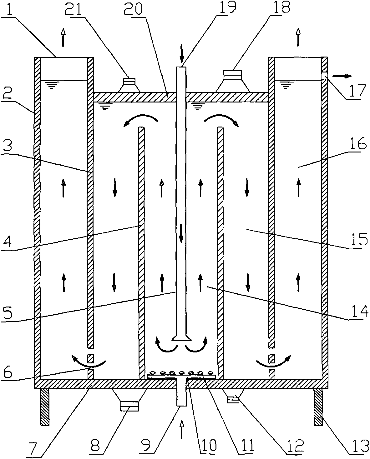
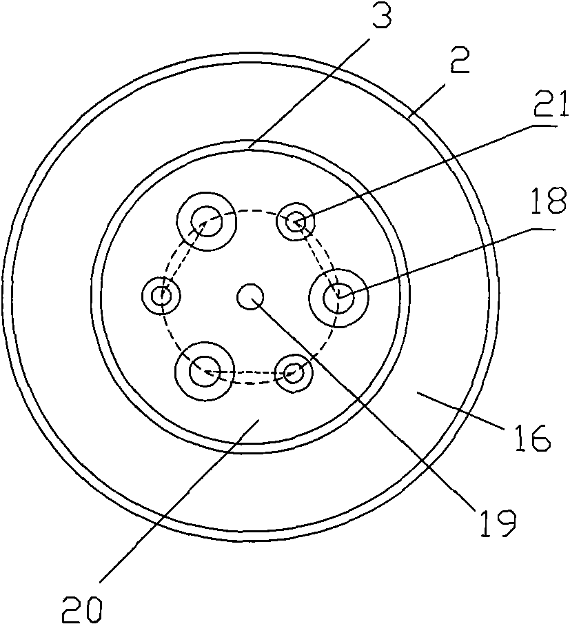
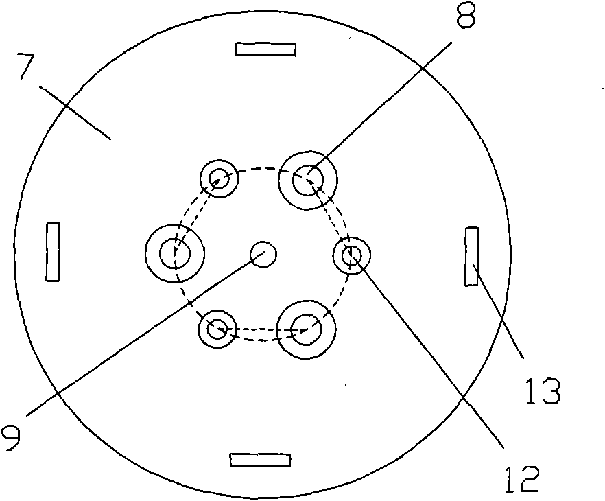
[0028] see figure 1 , figure 2 , image 3 with Figure 4 , in this embodiment, the reactor adopts a cylinder structure, including an outer cylinder 2, an inner cylinder 3, a bottom plate 7, a lifting cylinder 4 in the inner cylinder 3, and a water inlet pipe 5, and the water outlet 17 is arranged on the side of the outer cylinder 2 On the wall; a cover plate 20 is placed above the inner cylinder 3, and the height of the cover plate 20 is lower than the height of the water outlet 17; two sets of ultrasonic transducers placed outside the cylinder are respectively arranged on the cover plate 20 and the bottom plate 7 ; Among the two groups of ultrasonic transducers, one group is spaced from the top high-frequency ultrasonic transducer 18 and the top low-frequency ultrasonic transducer 21 and is evenly distributed on the cover plate 20; the other group is composed of the bottom high-frequency ultrasonic transducer The transducer 8 and the bottom low-frequency ultrasonic transd...

Embodiment 2

[0034] The overall structure of the reactor in this embodiment is the same as in Embodiment 1, except that the arrangement of the top high-frequency ultrasonic transducer 18 and the top low-frequency ultrasonic transducer 21 on the cover plate 20 is as follows: Figure 5 As shown, the layers are evenly arranged in circular rings, that is, they are uniformly distributed on each layer of circular rings. Actually, the number of layers of transducers can be set correspondingly according to the area of ​​the cover plate 20, which can be 2 to 5 layers. Correspondingly, the arrangement of the bottom high-frequency ultrasonic transducer 8 and the bottom low-frequency ultrasonic transducer 12 is as follows Image 6 shown.

[0035] Aerator 11 presses in the present embodiment Figure 7 Shown in a mesh arrangement.

[0036] The reaction process of the waste water of the reactor during operation is the same as that of Example 1.

[0037] In a specific implementation, the two groups of ul...


PUM


Abstract

The invention discloses a double-frequency ultrasonic chemical reactor which is characterized by adopting a cylinder body structure and comprising an outer cylinder, an inner cylinder, a bottom plate, a lifting cylinder in the inner cylinder, a water inlet pipe and a water outlet arranged on the side wall of the outer cylinder, wherein a cover plate is arranged on the inner cylinder; two groups of ultrasonic transducers outside the cylinder body are respectively arranged on the cover plate and the bottom plate; one group of ultrasonic transducers consist of top high-frequency ultrasonic transducers and top low-frequency ultrasonic transducers, which are mutually spaced and uniformly distributed on the cover plate; and the other group of ultrasonic transducers consist of bottom high-frequency ultrasonic transducers and bottom low-frequency ultrasonic transducers, which are vertically and relatively arranged on the bottom plate. The invention effectively enhances the distribution uniformity of an ultrasonic acoustic field in the reactor, obviously increases the ultrasonic cavitation efficiency, prolongs the service life of equipment and can be applied to various industrial waste water, particularly to the degradation of high-concentrated organic waste water.

Description

technical field [0001] The invention relates to a wastewater treatment device, which belongs to the technical field of environmental protection equipment, in particular to a dual-frequency ultrasonic chemical reactor. Background technique [0002] With the acceleration of the industrialization process, more and more sewage is discharged from the production process of factories and mines in various industries, and urban water pollution is becoming more and more serious. In particular, the refractory high-concentration organic wastewater discharged from the chemical industry and printing and dyeing industry has complex components and high concentrations of organic matter, which puts forward higher requirements for treatment processes and equipment. As a physical means and tool, ultrasonic technology has unique advantages in the treatment of refractory organic polluted wastewater. Ultrasonic degradation of organic matter mainly utilizes acoustic cavitation. Acoustic cavitatio...

Claims


Application Information

Patent Timeline
IPC IPC(8): C02F1/36
Inventor 程建萍唐志国陈长琦
Owner HEFEI UNIV OF TECH
Why Eureka
Try Eureka