IGCT (Integrated Gate Commutated Thyristor) frequency testing method and device

A test device and frequency characteristic test technology, applied in the field of IGCT frequency test method and device, can solve the problems of high cost and high complexity, and achieve the effect of low cost, strong adaptability and low cost

Inactive Publication Date: 2011-01-05
CSR ZHUZHOU ELECTRIC LOCOMOTIVE RES INST
View PDF2 Cites 8 Cited by
  • Summary
  • Abstract
  • Description
  • Claims
  • Application Information

AI Technical Summary

Problems solved by technology

[0003] Manufacturers such as ABB use a high-voltage, high-current h

Method used


Image

  • IGCT (Integrated Gate Commutated Thyristor) frequency testing method and device
  • IGCT (Integrated Gate Commutated Thyristor) frequency testing method and device
  • IGCT (Integrated Gate Commutated Thyristor) frequency testing method and device

Examples


Embodiment 1

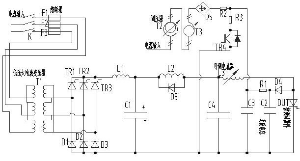
[0020] A device for IGCT frequency test proposed according to the above test method is: an IGCT frequency test device, including a low-voltage high-current phase-controlled rectifier circuit composed of a thyristor and a rectifier; a reactor for improving harmonics and current impact , and the main capacitor; the load reactor and its freewheeling diode; the adjustable reactor (or a group of reactors for combination) to simulate the turn-off overvoltage; the clamping circuit of the IGCT and the power supply for adjusting the clamping voltage, and A voltage regulation system to change the voltage of the clamp circuit and a chopper system to stabilize the voltage. The clamping circuit includes a clamping diode, a clamping capacitor, a clamping resistor, an adjustable voltage source connected to the clamping resistor, and a chopper for stabilizing the voltage source.

[0021] Such as figure 1 As shown, the described low-voltage high-current phase-controlled rectification circuit...

Embodiment 2

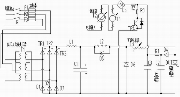
[0025] As another embodiment of the present invention, the figure 1 Replace C4 in the diode D6, such as figure 2 , then L3 forms a loop through D4, C2, and D6 to realize figure 1 The same function as the corresponding part in .

Embodiment 3

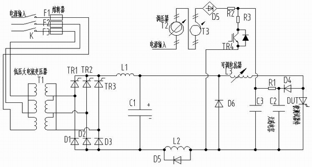
[0027] Of course you can also put figure 1 in L2 and D5 placed as in image 3 The functions of L2 and D5 are basically similar.

[0028] The characteristic of this frequency test device is that it adopts low voltage and high current, cooperates with adjustable clamping voltage to simulate the real working condition, and tests the frequency characteristics of IGCT. The device has low total power, low cost and strong adaptability.


PUM


Abstract

The invention relates to IGCT (Integrated Gate Commutated Thyristor) frequency testing method and device. The frequency test of an IGCT is realized by using low-voltage heavy current and adjustable clamping voltage to simulate the work condition of the IGCT through a group of low-voltage heavy-current phase control rectification circuits, a group of reactors, a capacitor and a clamping circuit ofa tested device, wherein each low-voltage heavy-current phase control rectification circuit comprises a thyristor and a rectifying tube; and the reactors are used for improving harmonic waves and current surge. When the tested device is turned on, voltage on main capacitor forms a loop by an inductor, the adjustable reactors and the tested device, current flows through the loop to change output voltage or the conduction time and the dutyfactor of the tested device, and namely that the conduction current of the tested device can be adjusted. When the tested device is turned off, the reactors follow current by a diode, the inductor forms a loop by a clamping diode and a clamping capacitor, the inductor generates voltage on the tested device at the same time, the voltage is influenced by thevoltage of the champing capacitor, and the turn-off voltage environment of the tested device can be changed by changing the voltage value of the clamping capacitor.

Description

technical field [0001] The invention relates to a performance testing method and device of an electrical component, in particular to an IGCT frequency testing method and device. It is mainly used for frequency characteristic test of IGCT. Background technique [0002] As one of the high-power full-control devices, IGCT has the characteristics of reduced conduction voltage and high switching frequency, and is widely used. Before IGCT is used, various parameters must be tested in detail. Frequency test is an important performance test, which has a great impact on reliability. [0003] Manufacturers such as ABB use a high-voltage, high-current high-power system for frequency testing, which is costly and complex. Therefore, it is necessary to design a device that can better simulate the real working conditions of the device, reduce costs, and facilitate operation. [0004] According to the working characteristics of the IGCT, its working conditions are divided into four state...

Claims


Application Information

Patent Timeline
IPC IPC(8): G01R31/28
Inventor 蒋耀生赵燕峰张劲松郭知彼
Owner CSR ZHUZHOU ELECTRIC LOCOMOTIVE RES INST
Why Eureka
Try Eureka