

Forming structure of fluorescent powder colloid of light-emitting module and manufacture method thereof
A light-emitting module and manufacturing method technology, applied in semiconductor/solid-state device manufacturing, electric solid-state devices, semiconductor devices, etc., can solve problems such as non-overlapping, yellowing of epoxy resin A3, glare, etc., to reduce material and manufacturing costs , improve the service life, reduce the effect of heat accumulation
- Summary
- Abstract
- Description
- Claims
- Application Information
AI Technical Summary
Problems solved by technology
Method used
Image

Examples
Embodiment Construction
[0036] In order to achieve the above-mentioned purpose and effect, the technical means and the structure adopted by the present invention, the features and functions of the preferred embodiments of the present invention will be described in detail as follows, so as to fully understand.
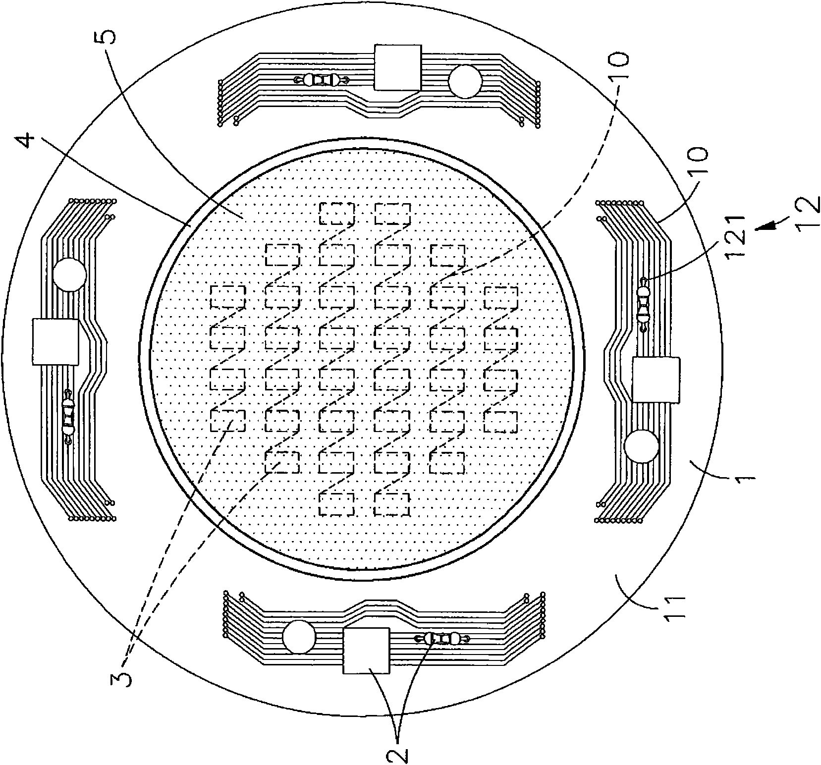
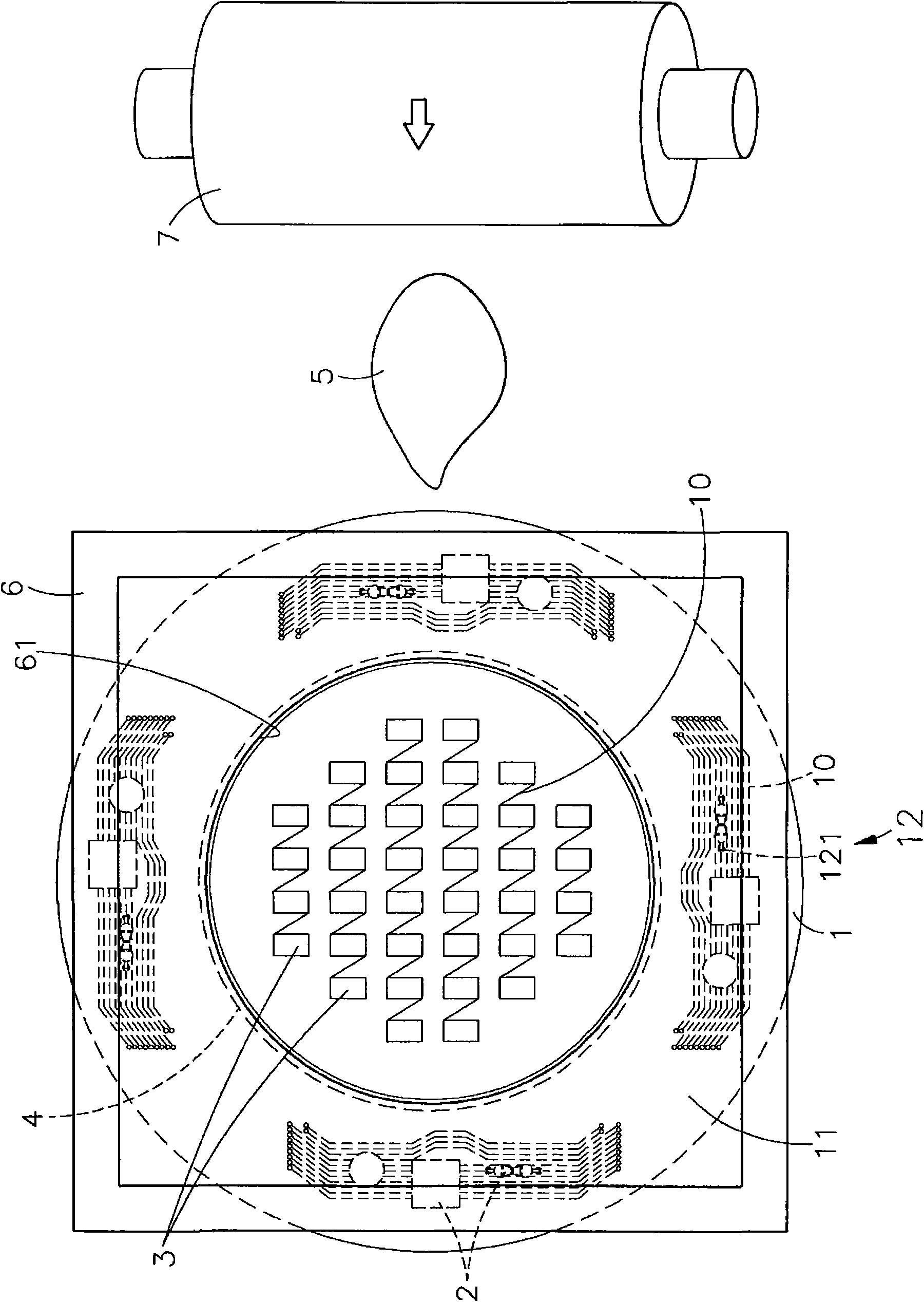
[0037] see figure 1 , Figure 5 As shown, it is a top view of the fluorescent powder colloidal molding structure of the preferred embodiment of the present invention and a partial side view of the light emitting module after the phosphor colloid is coated. It can be clearly seen from the figure that the light emitting module of the present invention includes There are circuit board 1, electronic components 2, luminous crystal grain 3, apron 4 and fluorescent powder colloid 5, among which:
[0038] The circuit board 1 has a plurality of lines 10 for circuit layout on one side surface 11, and a plurality of line contacts 12 are arranged on the lines 10, and the plurality of line contacts 12 in...
PUM
 Abstract
Description
Claims
Application Information