Permanent-magnet magnetic dehydrator

A dehydrator and magnetic technology, applied in the direction of magnetic separation, solid separation, chemical instruments and methods, etc., can solve the problems of backward technology, long production cycle, and large land occupation, and achieve simple process, short production cycle, and land occupation. small area effect

Inactive Publication Date: 2011-01-19
梧州市华友磁选机厂(普通合伙)
View PDF4 Cites 6 Cited by
  • Summary
  • Abstract
  • Description
  • Claims
  • Application Information

AI Technical Summary

Problems solved by technology

Large investment, large land occupation, two or three months for slurry precipitation, long production cycle and backward technology

Method used


Image

  • Permanent-magnet magnetic dehydrator
  • Permanent-magnet magnetic dehydrator
  • Permanent-magnet magnetic dehydrator

Examples


Embodiment Construction

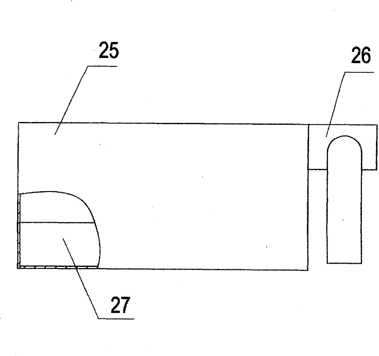
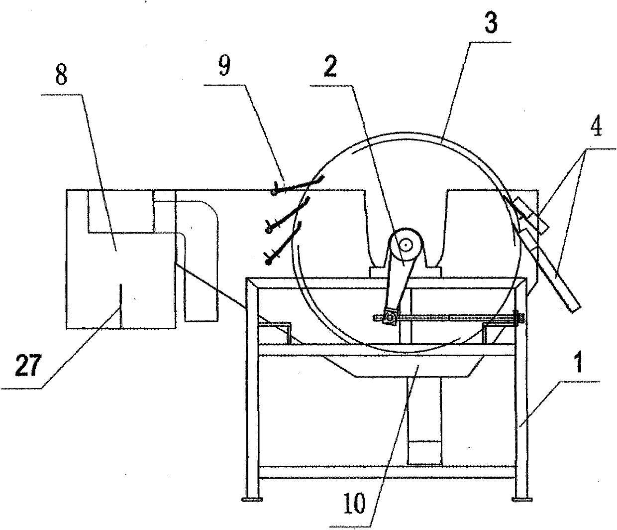
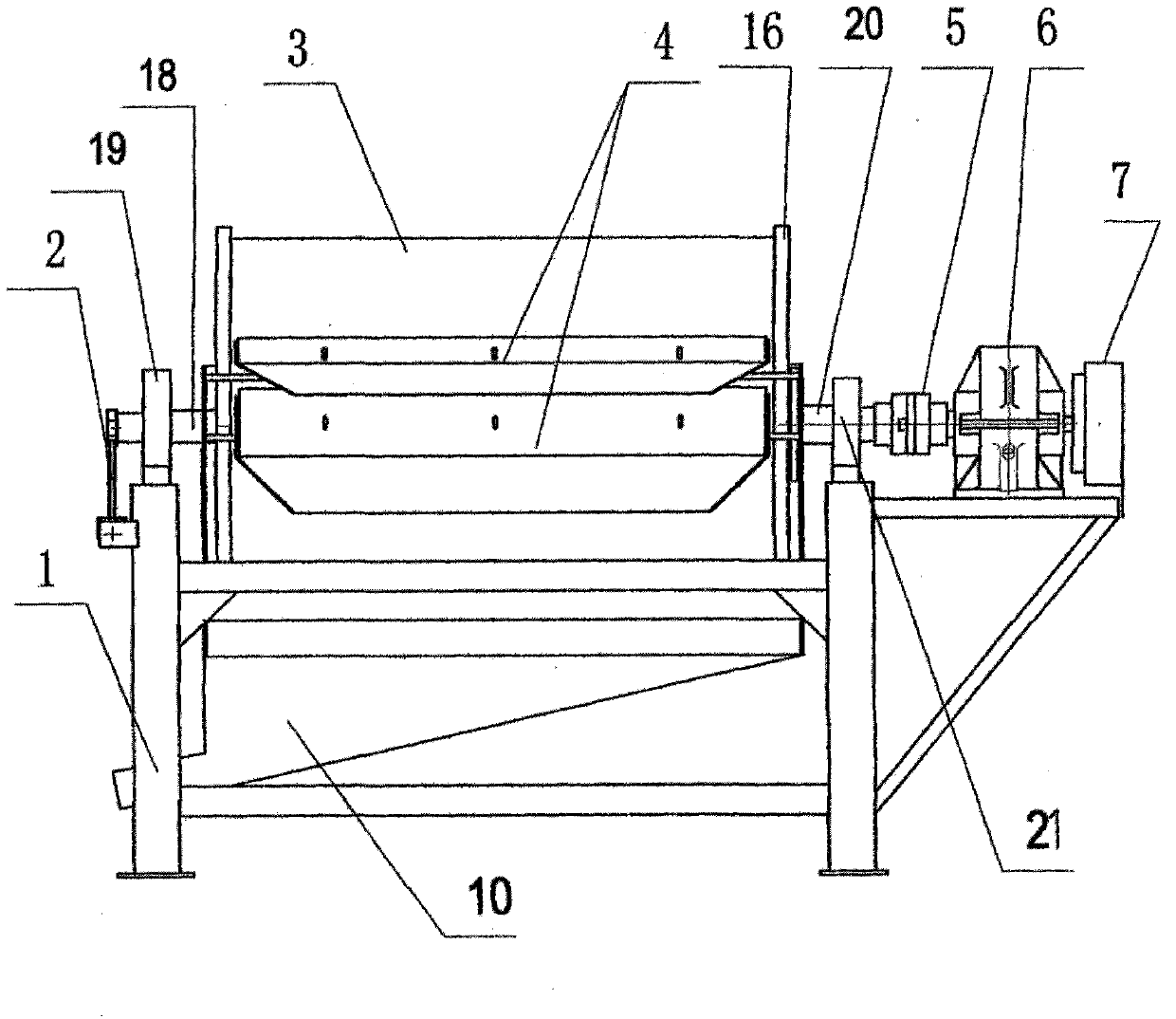
[0013] Referring to the accompanying drawings, the permanent magnetic dehydrator of the present invention includes a frame 1, a coupling 5, a speed reducer 6, a motor 7, and also includes a magnetic system adjustment device 2, a magnetic drum 3, a demineralization device 4, and an ore feeding device 8. Water pressure device 9, tank body 10; frame 1 is composed of power frame and main frame, the main frame is on the left, and the power frame is on the right, which are welded by channel steel and angle steel according to different specifications and models. Install the coupling 5, reducer 6, and motor 7 on the power frame of the frame 1, the pulley on the output shaft sleeve of the motor 7 is connected with the pulley on the input shaft of the reducer 6 through the belt, and the output shaft of the reducer 6 is connected through the coupling The device 5 is connected with the short shaft 20 of the magnetic drum 3; a bearing seat 21 is installed on one side of the main frame by th...


PUM


Abstract

The invention provides a permanent-magnet magnetic dehydrator. The permanent-magnet magnetic dehydrator comprises a frame 1, a magnetic system regulation device 2, a magnetic roller 3, a demineralizing device 4, a coupler 5, a speed reducer 6, a motor 7, a feeding device 8, a pressurized water device 9 and a groove body 10. The frame consists of a power frame and a main frame; the coupler 5, the speed reducer 6 and the motor 7 are arranged on the power frame; the motor is connected with the short shaft 20 of the magnetic roller 3 through the coupler 5; the groove body, the feeding device and the demineralizing device are connected together on the main frame; the pressurized water device is arranged on the two sides of the groove body; a bearing seat 21 and a support seat 19 of the magnetic roller are arranged on the surface of the main frame; and a wrench 12 of the magnetic system regulation device is sleeved on the shaft head of the magnetic system shaft 18 of the magnetic roller. The permanent-magnet magnetic dehydrator has the advantages of suitability for the line production of large-batch production, short production period, low investment and production cost, good dehydration effect, simple process, portability, small floor area, energy conservation, energy consumption reduction and convenient operation and maintenance.

Description

1. Technical field [0001] The invention relates to a device for dehydrating and concentrating magnetic materials; in particular, a device for dehydrating and concentrating iron concentrate after magnetic separation. 2. Background technology [0002] Iron ore concentrators have been using traditional sedimentation tanks for sedimentation and dehydration of iron concentrates, which are not suitable for the production requirements of large-scale flow operations. The investment is large, the land occupation is large, the slurry sedimentation time usually takes two to three months, the production cycle is long, and the technology is backward. 3. Contents of the invention [0003] The purpose of the present invention is to provide a permanent magnet magnetic dehydrator for dehydrating and concentrating iron ore by using a brand-new method combining magnetism and mechanics. The dehydration machine can adapt to the flow operation of mass production, has short production cycle, lo...

Claims


Application Information

Patent Timeline
Patent Type & Authority Applications(China)
IPC IPC(8): B03C1/30
Inventor 张明华刘君成欧阳峻
Owner 梧州市华友磁选机厂(普通合伙)
Why Eureka
Try Eureka