Flue gas desulfurization equipment and method for float glass exhaust-heat boiler

A waste heat boiler and float glass technology, applied in lighting and heating equipment, separation methods, chemical instruments and methods, etc., can solve the problems of low utilization rate of waste heat of flue gas, waste, inconvenient maintenance, etc., and achieve easy management and maintenance, Improve waste heat utilization rate and save floor space

Active Publication Date: 2011-01-26
CHENGDU HOT NEW ENERGY TECH
View PDF3 Cites 4 Cited by
  • Summary
  • Abstract
  • Description
  • Claims
  • Application Information

AI Technical Summary

Problems solved by technology

[0003] Desulfurization using the above process has the following disadvantages: 1. The flue set is complicated, maintenance is inconvenient, and the cost of flue gas treatment is high; Corrosion of the flue, fan or chimney due to the lowering of the flue gas temperature. At the same time, the flue gas temperature required for dry or semi-dry desulfurization must be ensured. After the heat is absorbed by the waste heat boiler, there is still a lot of heat left, and the waste heat utilization rate of the flue gas is low; 3. The flue gas is only desulfurized by the desulfurization device, and the desulfurization is not thorough enough; 4. There are still many flue gases discharged from the chimney. of polluting gases such as NO and NO 2
[0004] In addition, flue gas produced by thermal power plants is often desulfurized by ammonia desulfurization absorption towers. This ammonia desulfurization process can not only desulfurize flue gas, but also recycle and reuse the product thiamine after desulfurization. There are still a lot of gases that pollute the environment in the flue gas, such as NO and NO 2 , and the utilization rate of ammonia in this process is not high, and there are more escapes, resulting in waste
The ammonia desulfurization absorption tower is generally connected to the chimney through a connecting pipe, and the flue gas in the absorption tower is discharged into the atmosphere through the connecting pipe and the chimney. Due to the large number of connecting pipes and chimneys, the desulfurization process occupies a large area and costs high

Method used


Image

  • Flue gas desulfurization equipment and method for float glass exhaust-heat boiler
  • Flue gas desulfurization equipment and method for float glass exhaust-heat boiler

Examples


Embodiment

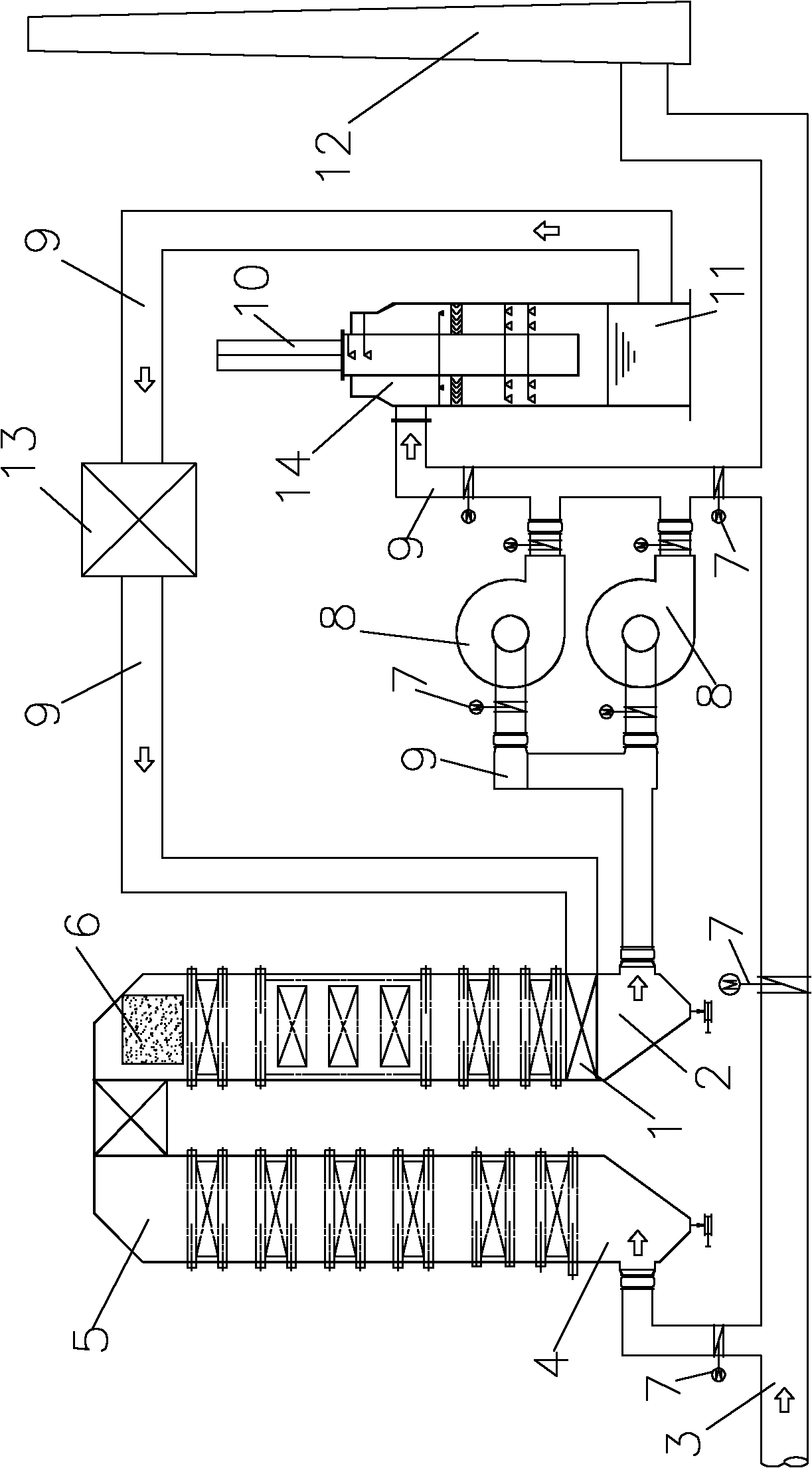
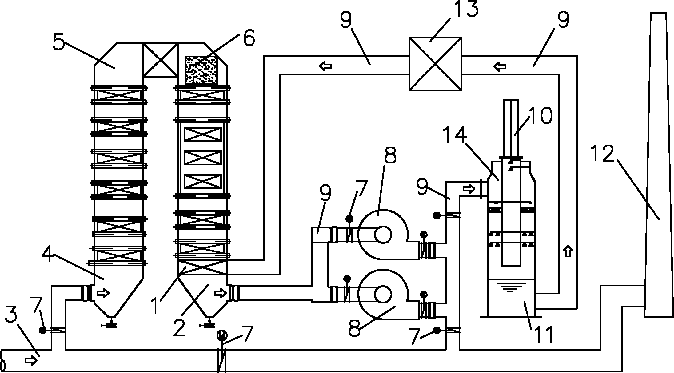
[0044] like figure 1 As shown in the figure, the flue gas desulfurization equipment of the float glass waste heat boiler includes the kiln flue gas conveying main pipe 3, the waste heat boiler 5 and the desulfurization device. The desulfurization device is an ammonia desulfurization absorption tower 14, and the boiler inlet of the waste heat boiler 5 The flue port 4 is connected to the main pipe 3 for conveying the kiln flue gas, and the boiler smoke outlet 2 of the above-mentioned waste heat boiler 5 is connected to the absorption tower smoke inlet of the ammonia desulfurization absorption tower 14 through two fans 8 and connecting pipes 9. The above-mentioned The top of the ammonia desulfurization absorption tower 14 is provided with an absorption tower exhaust pipe 10, the dew point temperature of the flue gas at the boiler flue gas outlet 2 is T2, and the actual temperature of the flue gas at the boiler flue gas outlet 2 is T1. The range of T1 is 15°C≤(T1-T2)≤25°C, and a d...


PUM


Abstract

The invention discloses flue gas desulfurization equipment and a flue gas desulfurization method for float glass exhaust-heat boiler, which can improve the utilization rate of exhaust heat of the fuel gas in the exhaust-heat boiler. The equipment comprises a kiln fuel gas conveying pipe, the exhaust-heat boiler and a desulfurization device, wherein the desulfurization device is an ammonia-processdesulfurization absorption tower; in addition, a denitration device can be arranged in the exhaust-heat boiler for removing a nitric oxide pollution source from the fuel gas, and thus environmental protection is promoted. The fuel gas temperature required by ammonia-process desulfurization is low, so the fuel gas temperature at the fuel opening of the boiler can be kept at a low value for improving the utilization rate of the exhaust heat. Besides, an absorption tower fuel gas outlet pipe is arranged on the top of the ammonia-process desulfurization absorption tower; and thus, the fuel gas inthe ammonia-process desulfurization absorption tower can be discharged into the atmosphere directly, the fuel gas processing is simplified and the fuel gas processing cost is reduced.

Description

technical field [0001] The invention relates to a flue gas desulfurization equipment and method, in particular to a flue gas desulfurization equipment and method of a float glass waste heat boiler. Background technique [0002] At present, the flue gas desulfurization process of the float glass production line generally includes the kiln flue gas conveying main pipe, flue (connecting pipe), fan, waste heat boiler, desulfurization device and chimney, and the waste heat boiler and desulfurization device in this desulfurization process are set independently The flue gas in the main pipe can directly flow into the desulfurization device through the flue and the desulfurization fan. After desulfurization treatment, the flue gas enters the chimney through the flue and is discharged to the atmosphere from the chimney; After heat exchange, the flue gas enters the desulfurization device through the induced draft fan and the flue. After desulfurization treatment, this part of the flue...

Claims


Application Information

Patent Timeline
IPC IPC(8): B01D53/76B01D53/50F27D17/00C03B18/00
CPCY02P10/25
Inventor 黄浩石瑞祥赵学明肖峰
Owner CHENGDU HOT NEW ENERGY TECH
Why Eureka
Try Eureka