Heat-insulating material
A technology of thermal insulation material and resin foam, which is used in thin material processing, heat exchange equipment, and pipeline protection through thermal insulation. , The effect of long-term maintenance of thermal insulation and excellent environmental performance
- Summary
- Abstract
- Description
- Claims
- Application Information
AI Technical Summary
Problems solved by technology
Method used
Image

Examples
manufacture example
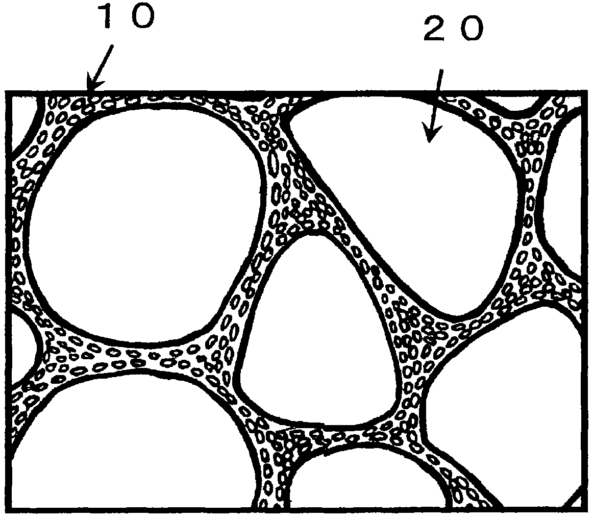
[0061] As a specific production example of the resin foam by "method 2", mixing polylactic acid and polymethyl methacrylate and foaming it to form pores (L), and then dissolving only polymethacrylic acid A method of decomposing the polymethyl methacrylate with a solvent of methyl ester (toluene-hexane solution, etc.) to generate pores (S) around the pores (L); mixing polystyrene and polylactic acid and making it A method in which pores (L) are generated by foaming, and then only polylactic acid is hydrolyzed to generate pores (S) around the pores (L).
[0062] Here, examples of the foaming agent used in "Method 1" and "Method 2" include chemical foaming agents that generate various gases by thermal decomposition, and physical foaming agents that use various gases themselves. In extrusion foaming, either a chemical foaming agent or a physical foaming agent can be preferably used, and in the batch foaming method, a physical foaming agent is preferably used.
[0063] As chemical...
Embodiment 1
[0213] Using a tandem extruder equipped with a supercritical carbon dioxide supply line, mix the particles of resin (A-1) and resin (A-2) according to the ratio in the table, and supply it to the first extruder. It is melted under the pressure, and then supercritical carbon dioxide is supplied through the front end of the extruder. Next, the temperature was lowered to 170° C. in the second extruder, and it was discharged into the air from a 10 cm long slit die to obtain a resin foam with a thickness of 10 mm. The carbon dioxide gas solubility of the resin (A-1) was 5.5%, and the carbon dioxide gas solubility of the resin (A-2) was 3.7%.
[0214] Table 2 shows the evaluation results of this resin foam. The porosity (X) is 97%, and the number density of pores (L) is 10 6 piece / mm 2 , the number density of pores (S) is 10 6 pieces / μm 2 .
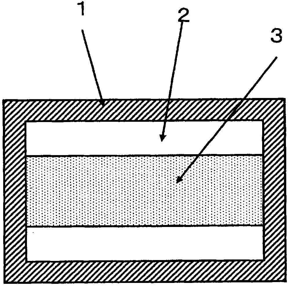
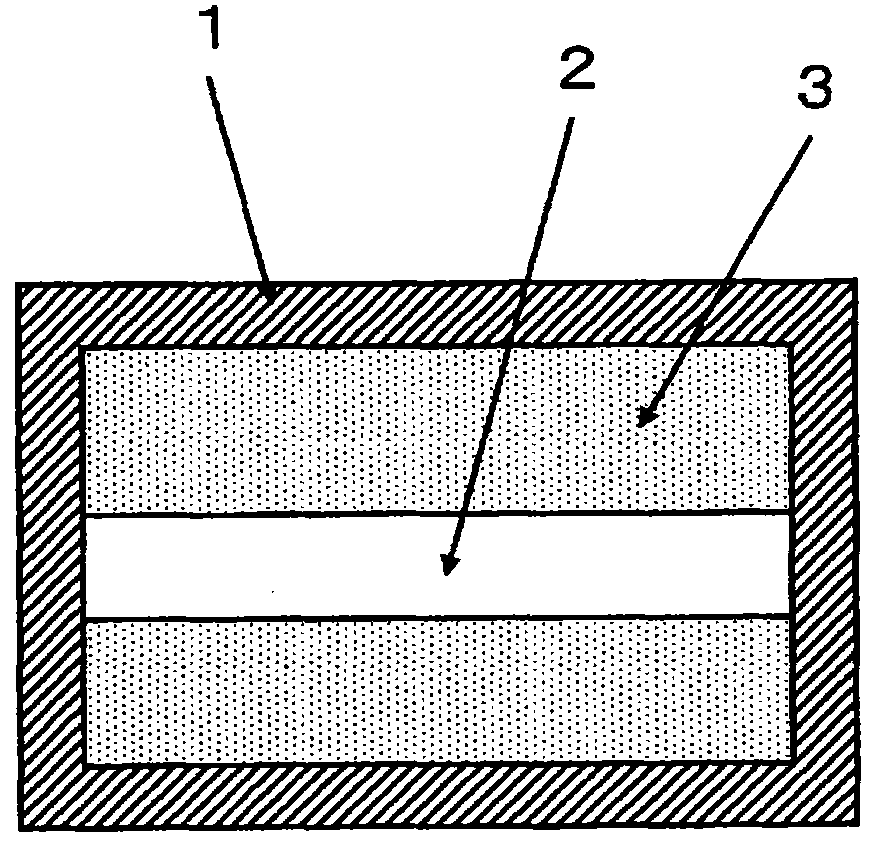
[0215] Next, the resin (B-1) was supplied to a single-screw extruder, heated to 160 to 280° C., and extruded in a sheet form from a T-di...
Embodiment 2
[0221] A resin foam having a thickness of 10 mm was obtained by extrusion foaming in the same manner as in Example 1 using the resin (A-1) and the resin (A-3). The carbon dioxide gas solubility of the resin (A-1) was 5.5%, and the carbon dioxide gas solubility of the resin (A-3) was 9.0%. Table 2 shows the evaluation results of this resin foam. The porosity (X) is 95%, the number density (L) is 10 6 piece / mm 2 , the number density (S) is 10 5 pieces / μm 2 .
[0222] Next, the pellets of resin (B-1) and resin (B-2) were mixed in a weight ratio of 40:60 and supplied to a two-layer laminated sleeve (pinol) immediately in front of the T-shaped mold. Extruder A. Then, the resin (B-3) was supplied to the extruder B connected to the above-mentioned sleeve and short tube. Heat the extruders A and B to 160-280°C and 160-240°C respectively, and use the extruder A and extruder B to form a sheet from the T-die with a lamination ratio (thickness) of 4:1. shape extrusion. The extrud...
PUM
 Abstract
Description
Claims
Application Information
 - Generate Ideas
- Intellectual Property
- Life Sciences
- Materials
- Tech Scout
- Unparalleled Data Quality
- Higher Quality Content
- 60% Fewer Hallucinations
Browse by: Latest US Patents, China's latest patents, Technical Efficacy Thesaurus, Application Domain, Technology Topic, Popular Technical Reports.
© 2025 PatSnap. All rights reserved.Legal|Privacy policy|Modern Slavery Act Transparency Statement|Sitemap|About US| Contact US: help@patsnap.com