
Variable gain filter circuit for WCDMA and GSM multi-mode transmitter

A filter and transmitter technology, applied in gain control, electrical components, amplification control, etc., can solve the problems of inappropriate low-cost high-integration CMOS process, large, unfavorable resistance value matching, etc., to reduce the impact , the effect of improving flexibility and reducing power consumption

Inactive Publication Date: 2011-02-02
FUDAN UNIV
View PDF5 Cites 7 Cited by
  • Summary
  • Abstract
  • Description
  • Claims
  • Application Information

AI Technical Summary

Problems solved by technology

For the analog baseband, the most commonly used technique is to use a separate variable gain amplifier and adjust it with the R-αR network, but the disadvantage of this method is that in order to achieve 1dB accuracy, α needs a large value, which is not conducive to the resistance value. match
Another solution is to use the logarithmic characteristics of bipolar transistors to achieve logarithmic linear adjustment of the gain, but it is not suitable for low-cost and highly integrated CMOS processes.

Method used


Image

  • Variable gain filter circuit for WCDMA and GSM multi-mode transmitter
  • Variable gain filter circuit for WCDMA and GSM multi-mode transmitter
  • Variable gain filter circuit for WCDMA and GSM multi-mode transmitter

Examples


Embodiment Construction

[0028] The present invention will be described in further detail below in conjunction with the accompanying drawings.

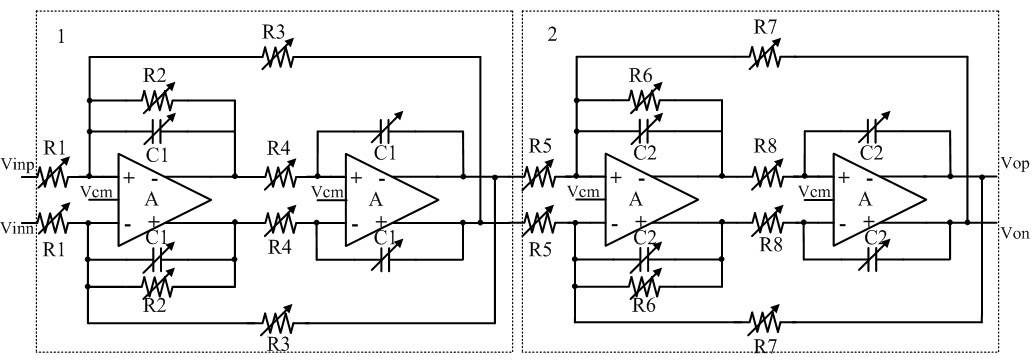
[0029] Such as figure 1 as shown, figure 1 The schematic diagram of the circuit structure of the variable gain filter in the WCDMA and GSM multimode transmitter provided by the present invention, the circuit is composed of two Tow-Thomas biquad circuits (1, 2) connected in series. It specifically includes four operational amplifier units (A), bandwidth adjustment units (C1, C2, R2, R6), filter quality factor adjustment units (R3, R4, R7, R8) and gain adjustment units (R1, R5).

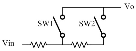
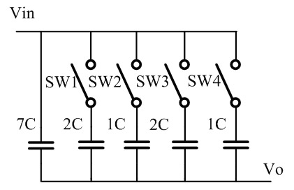
[0030]First, determine the bandwidth and quality factor of the two Tow-Thomas biquad circuits (1, 2) according to the bandwidth and structural form of the required filter. Since the bandwidth is determined by the product of resistors and capacitors, the values ​​of resistors and capacitors should be selected respectively. Since the transmitter is not very demanding on the noise of t...


PUM


Abstract

The invention belongs to the technical field of multi-mode radio frequency transmitters, in particular to a filter circuit with adjustable bandwidth and variable gain for a wideband code division multiple access (WCDMA) and global system for mobile communication (GSM) multi-mode transmitter. The circuit has a four-order active resistance-capacitance structure consisting of two Tow-Thomas dual second-order circuits which are connected in series, and comprises four operational amplifiers with the same structure, a bandwidth adjustment unit, a filter quality factor adjustment unit and a gain adjustment unit, wherein the operational amplifiers adjust unit gain bandwidth and direct current offset of the filter in two different modes; the bandwidth adjustment unit adjusts the cut-off frequency of the filter by varying the resistance-capacitance value; and the gain adjustment unit varies the gain by adjusting the resistance value on the premise of not varying the bandwidth of the filter. By using the circuit, the filter function and the gain adjustment function in the multi-mode transmitter can be realized with low power consumption by using a simple circuit.

Description

technical field [0001] The invention belongs to the technical field of multi-mode radio frequency transmitters, in particular to a filter and gain adjustment circuit for analog baseband. Background technique [0002] Multi-mode wireless transceivers are research hotspots in recent years, in which the transmitter mainly includes a digital baseband part, which mainly completes the processing of the digital part; it reaches the analog baseband part through a digital-to-analog converter, and mainly completes filtering and gain adjustment functions; and then reaches the RF front end, Modulate the analog baseband signal up to the radio frequency signal and transmit it through the antenna. For a multi-mode transmitter, it is hoped that the hardware part can be multiplexed to the greatest extent so as to save power consumption and reduce costs. [0003] For the WCDMA protocol, since different users occupy the same channel, in order to reduce mutual interference, it is hoped that th...

Claims


Application Information

Patent Timeline
IPC IPC(8): H04B1/04H03G3/12H03H7/06
Inventor 孙瑜李歆洪志良
Owner FUDAN UNIV
Learn More