

Power conversion device
A power conversion device and power conversion technology, which is applied in the direction of output power conversion devices, circuits, electrical components, etc., can solve the problems of increased switching loss, large-scale cooling structure, and increased cost, achieving high-efficiency power conversion and reducing wiring inductance Effect
- Summary
- Abstract
- Description
- Claims
- Application Information
AI Technical Summary
Problems solved by technology
Method used
Image

Examples
Embodiment approach 1
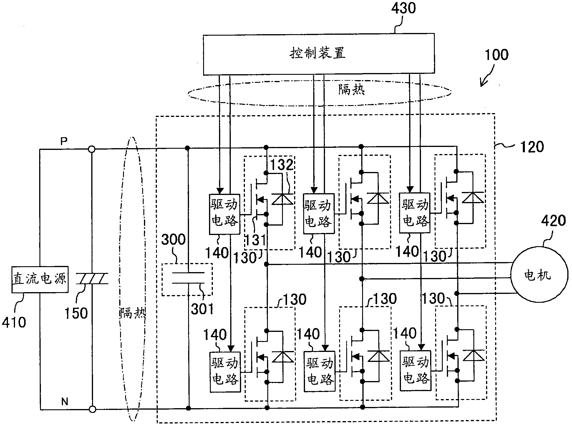
[0087] figure 1 The configuration of the power conversion device according to Embodiment 1 of the present invention is shown. This power conversion device 100 has a smoothing capacitor 150 and an inverter circuit 120 . The inverter circuit 120 controlled by a control device 430 converts DC input from a DC power supply 410 into three-phase AC, and supplies the three-phase AC motor 420 . The three-phase AC motor 420 is used to drive the compressor provided in the refrigerant circuit of the air conditioner. In addition, the DC power supply 410 may be constituted by, for example, an inverter circuit or the like for rectifying an AC power supply such as a commercial AC power supply.
[0088] The smoothing capacitor 150 is a capacitor that smoothes the voltage of the DC power supply. The smoothing capacitor 150 can be, for example, an electrolytic capacitor. The upper limit of the allowable temperature of the electrolytic capacitor is about 100° C., so in the present embodiment, ...
Embodiment approach 2
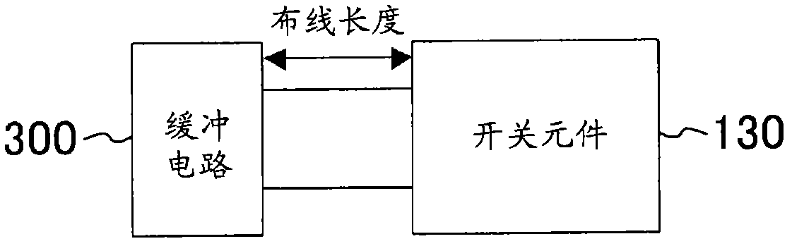
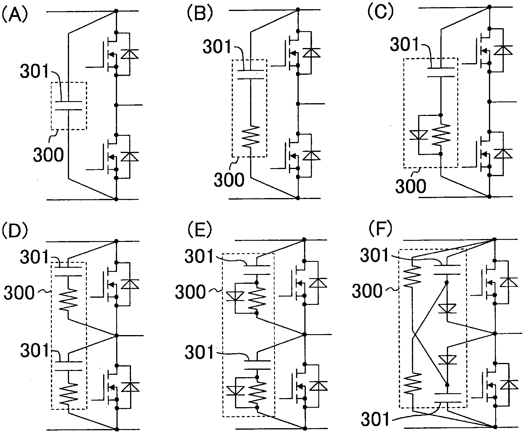
[0114] Figure 4 is an example in which a snubber circuit is provided for each phase of the switching element 130 . In this example, these snubber circuits use image 3 The snubber circuit shown in B. In addition, the driving circuit and the like are omitted in this figure. In this inverter circuit 120, each constituent element is also constituted using only components capable of operating at 150° C. or higher.
[0115] The "phase" mentioned here refers to the part where the switching elements 130 are connected in series (in Figure 4 middle finger series circuit 170). Such a snubber circuit arrangement is effective when wiring inductance between phases becomes a problem, as in high-speed switching.
Embodiment approach 3
[0117] In Embodiment 3 of the present invention, an example in which a power conversion device is used for a heat pump device will be described.
[0118] The heat pump device according to Embodiment 3 of the present invention constitutes an air conditioner 1 that switches between indoor cooling and heating. Such as Figure 5 As shown, the air conditioning device 1 has a refrigerant circuit 10 . Freon refrigerant is filled in the refrigerant circuit 10 as a refrigerant. The refrigerant circulates in the refrigerant circuit 10 to perform a vapor compression refrigeration cycle.
[0119]
[0120] A compressor 20 , an indoor heat exchanger 21 , an expansion valve 22 , an outdoor heat exchanger 23 , and a four-way switching valve 24 are connected to the refrigerant circuit 10 . The compressor 20 of Embodiment 3 is a rotary compressor and constitutes the fluid machine of the present invention. The details of the compressor 20 will be described later. The indoor heat exchanger...
PUM
 Abstract
Description
Claims
Application Information