Magnetic suspension bearing of hybrid magnetic circuit

A magnetic levitation bearing and hybrid magnetic circuit technology, applied in the direction of bearings, shafts and bearings, mechanical equipment, etc., can solve the problems of large electric power, high weight, large volume, etc., achieve low loss and temperature rise, small volume, and good control characteristics Effect

Active Publication Date: 2012-08-08
HARBIN INST OF TECH
View PDF0 Cites 2 Cited by
  • Summary
  • Abstract
  • Description
  • Claims
  • Application Information

AI Technical Summary

Problems solved by technology

[0004] In order to solve the defects of large electric power, large volume and high weight of existing magnetic suspension bearings, the present invention proposes a new hybrid magnetic circuit magnetic suspension bearing

Method used


Image

  • Magnetic suspension bearing of hybrid magnetic circuit
  • Magnetic suspension bearing of hybrid magnetic circuit
  • Magnetic suspension bearing of hybrid magnetic circuit

Examples


specific Embodiment approach 1

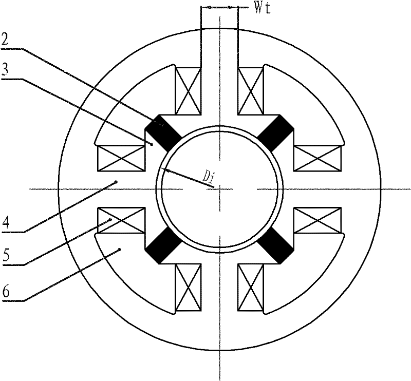
[0010] Embodiment 1: The hybrid magnetic circuit magnetic suspension bearing of this embodiment is composed of a stator, a rotor and an air gap. The stator is composed of a stator core, an excitation coil 5 and an excitation permanent magnet 2. The end face of the stator core is circular, and on the side of the stator In the wall, there are four through holes 6 with fan-shaped end faces along the moving direction of the rotor. The four through holes 6 have the same shape and are distributed symmetrically with the central axis of the stator. Between two adjacent through holes 6 are Stator teeth 4, the width W of the stator teeth 4 along the circumferential direction t Meet the conditions: W t i / 4, where D i is the inner diameter of the stator core, each stator tooth 4 is wound with an excitation coil 5, the part between the outer wall of the stator and the tooth root of the stator tooth 4 is an annular yoke, and the part between the four through holes 6 of the stator and the ...

specific Embodiment approach 2

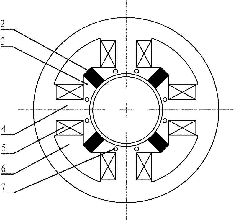
[0012] Specific implementation mode two: see figure 2 This embodiment will be described. The difference between the present embodiment and the first embodiment is that an axial magnetic isolation hole 7 is provided at the connection between each stator tooth 4 and the adjacent permanent magnet collecting yoke 3 .

[0013] In this embodiment, a magnetic isolation hole 7 is added at the connection between the permanent magnet yoke 3 and the stator tooth 4, which can effectively reduce the mutual influence between the magnetic flux of the permanent magnet 2 and the electric excitation flux, and improve the control accuracy of the bearing.

specific Embodiment approach 3

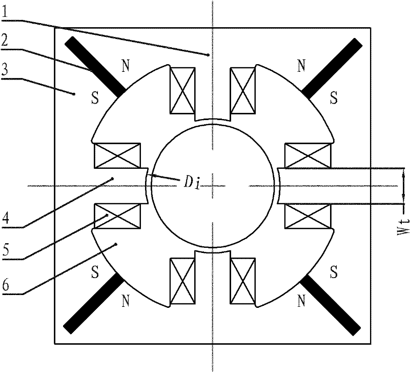
[0014] Specific Embodiment Three: The hybrid magnetic circuit magnetic suspension bearing of this embodiment is mainly composed of a stator, a rotor and an air gap. The stator includes a stator core, an excitation coil 5 and an excitation permanent magnet 2. The inner wall of the stator core is evenly distributed along the circumferential direction with four stator teeth. 4. The width W of each stator tooth 4 along the circumferential direction t Meet the conditions: W t i / 4, where D i is the inner diameter of the stator core, and each stator tooth 4 is wound with an excitation coil 5; between every two adjacent stator teeth 4 is the groove of the stator core, and the part of the stator core located at the root of the stator teeth 4 is the magnetic yoke 1, The stator core part between two adjacent stator teeth 4 is a permanent magnet poly yoke 3, and the permanent magnet poly yoke 3 is a mirror symmetrical structure. On the inner wall of each permanent magnet poly yoke 3, al...


PUM


Abstract

The invention provides a magnetic suspension bearing of a hybrid magnetic circuit, which relates to the technical field of magnetic suspension bearings. The invention overcomes the defects of large electric power, large volume and heavy weight of the existing magnetic suspension bearing. Four stator teeth in a stator core in the magnetic suspension bearing of the hybrid magnetic circuit of the invention are uniformly distributed on the inner surface of an annular yoke in an angle of 90 degrees, and the width Wt of the stator teeth in the circumferential direction meets the following condition: Wt<pi Di / 4, wherein Di represents the inner diameter of the stator core. A magnetism gathering yoke of a permanent magnet is arranged between the tooth ends of every two adjacent stator teeth facingan air gap, a parallel slot is formed on the bisector of the magnetism gathering yoke of the permanent magnet along the radial direction, a permanent magnet in a flat structure is embedded in the slot, and the permanent magnet is magnetized in parallel along the tangential direction. A rotor is cylindrical or tubular and is composed of a magnetism guiding ring and a rotating shaft, and the magnetism guiding ring is sleeved outside the cylindrical or tubular rotating shaft. The magnetic suspension bearing of the hybrid magnetic circuit of the invention has the advantages of low loss, low temperature rise, good control characteristic, small volume, light weight and wide application prospect.

Description

technical field [0001] The invention relates to a magnetic suspension bearing. Background technique [0002] Magnetic bearing, also known as active magnetic suspension bearing, is a new type of high-performance bearing without mechanical contact between the rotor and the stator. Compared with traditional ball bearings, sliding bearings and oil film bearings, magnetic suspension bearings use electromagnetic force to suspend the rotor in space, there is no mechanical contact between the stator and rotor, and the rotor can reach a very high speed, with small mechanical wear and energy consumption. Low noise, long life, no lubrication, no oil pollution, etc., especially suitable for special environments such as high speed, vacuum, and ultra-clean. It can be widely used in the fields of mechanical processing, turbomachinery, aerospace, petroleum and petrochemical, vacuum technology, energy, rotor dynamics characteristics identification and testing, and is recognized as a promisi...

Claims


Application Information

Patent Timeline
Patent Type & Authority Patents(China)
IPC IPC(8): F16C32/04
Inventor 寇宝泉贵献国刘奉海
Owner HARBIN INST OF TECH
Why Eureka
Try Eureka