Determination of local SAR in vivo and electrical conductivity mapping

A technology of permittivity and absorption rate, applied in the field of diagnosis, which can solve problems such as discontinuity

Inactive Publication Date: 2011-02-23
KONINK PHILIPS ELECTRONICS NV
View PDF3 Cites 10 Cited by
  • Summary
  • Abstract
  • Description
  • Claims
  • Application Information

AI Technical Summary

Problems solved by technology

Then divide the curl by E z , in some regions E z may be zero, causing a discontinuity

Method used


Image

  • Determination of local SAR in vivo and electrical conductivity mapping
  • Determination of local SAR in vivo and electrical conductivity mapping
  • Determination of local SAR in vivo and electrical conductivity mapping

Examples


Embodiment Construction

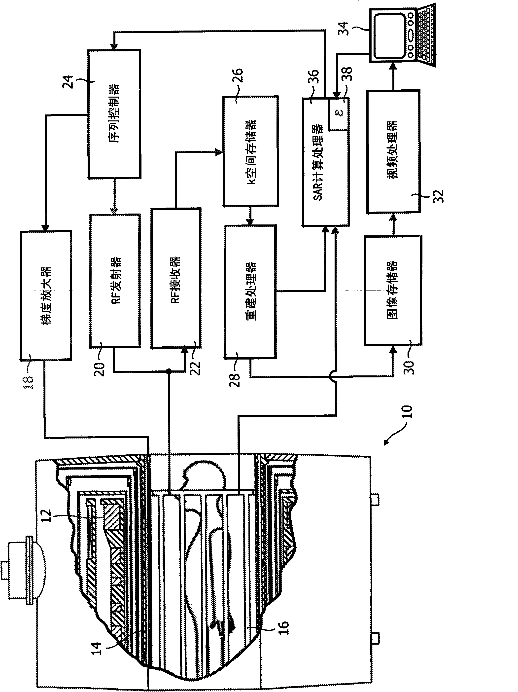
[0024] refer to figure 1 , shows a magnetic resonance scanner 10 . The magnetic resonance scanner 10 is illustrated as a closed bore system including a solenoid-shaped main magnet assembly 12, although open and other magnet configurations are also contemplated. The main magnet assembly 12 produces a substantially constant main magnetic field B oriented along the horizontal axis of the imaging region 0 . It is understood that other magnet arrangements are also contemplated, such as vertical and other configurations. The main magnet 12 in a bore system may have a field strength of about 0.5T to 7.0T or higher.

[0025] The gradient coil assembly 14 generates magnetic field gradients in the imaging region to spatially encode the main magnetic field. Preferably, the magnetic field gradient coil assembly 14 includes coil segments configured to generate magnetic field gradient pulses in three orthogonal directions, typically the longitudinal or z direction, the transverse or x d...


PUM


Abstract

A magnetic resonance imaging apparatus produces calculations of local specific energy absorption rates (SAR) by calculating an electrical permittivity map of a subject. The electric permittivity is calculated by measuring the components of the B1 field induced by a radio frequency (RF) coil (16). The Hx and Hy components of the B1 field can be directly measured. The Hz component is measured by encoding it into the phase of the resonance signals. Alternately, Hz can be calculated by solving Gauss's law for magnetism. Hz can also be estimated by finding the z component of the electric field. In the specific case of a birdcage RF coil, Hz can be estimated by using a model of the RF coil and a subject, a model of the RF coil alone, or setting Hz to a constant.

Description

technical field [0001] This application relates to the field of diagnostics. This application finds particular application in determining specific energy absorption in conjunction with magnetic resonance imaging and will be described with particular reference thereto. It is to be understood, however, that the present application applies more generally to mapping conductivity and permittivity of a patient in an MR environment and is not necessarily limited to the applications described above. Background technique [0002] A significant concern with imaging in high-field environments is that certain areas of the patient may absorb too much energy, causing pain, discomfort, and even injury to the patient. Consider the complex system of Specific Energy Absorption Rate (SAR) limitations to ensure that heating of the patient does not result in tissue damage. Localized SAR issues also often prohibit scanning patients with metal implants (eg, cardiac pacemakers, deep brain stimula...

Claims


Application Information

Patent Timeline
Patent Type & Authority Applications(China)
IPC IPC(8): G01R33/58A61B5/053
CPCG01R33/583A61B5/055G01R33/288
Inventor S·魏斯U·卡切尔P·韦尔尼科尔T·R·福格特C·芬德科里
Owner KONINK PHILIPS ELECTRONICS NV
Why Eureka
Try Eureka