Temperature detecting circuit

A temperature detection circuit, temperature value technology, applied in thermometers, thermometers with analog-to-digital converters, and heat measurement, etc., can solve problems such as difficulties, achieve the effect of suppressing cost increase, satisfying insulation and high responsiveness

Inactive Publication Date: 2011-03-02
KK TOSHIBA
View PDF1 Cites 10 Cited by
  • Summary
  • Abstract
  • Description
  • Claims
  • Application Information

AI Technical Summary

Problems solved by technology

Since the temperature detection circuit that transmits temperature information from the sensor to the microcontroller also needs to be insulated, it is difficult to extract the temperature information with the highest temperature in the stage of the temperature detection circuit

Method used


Image

  • Temperature detecting circuit
  • Temperature detecting circuit
  • Temperature detecting circuit

Examples


Embodiment 1

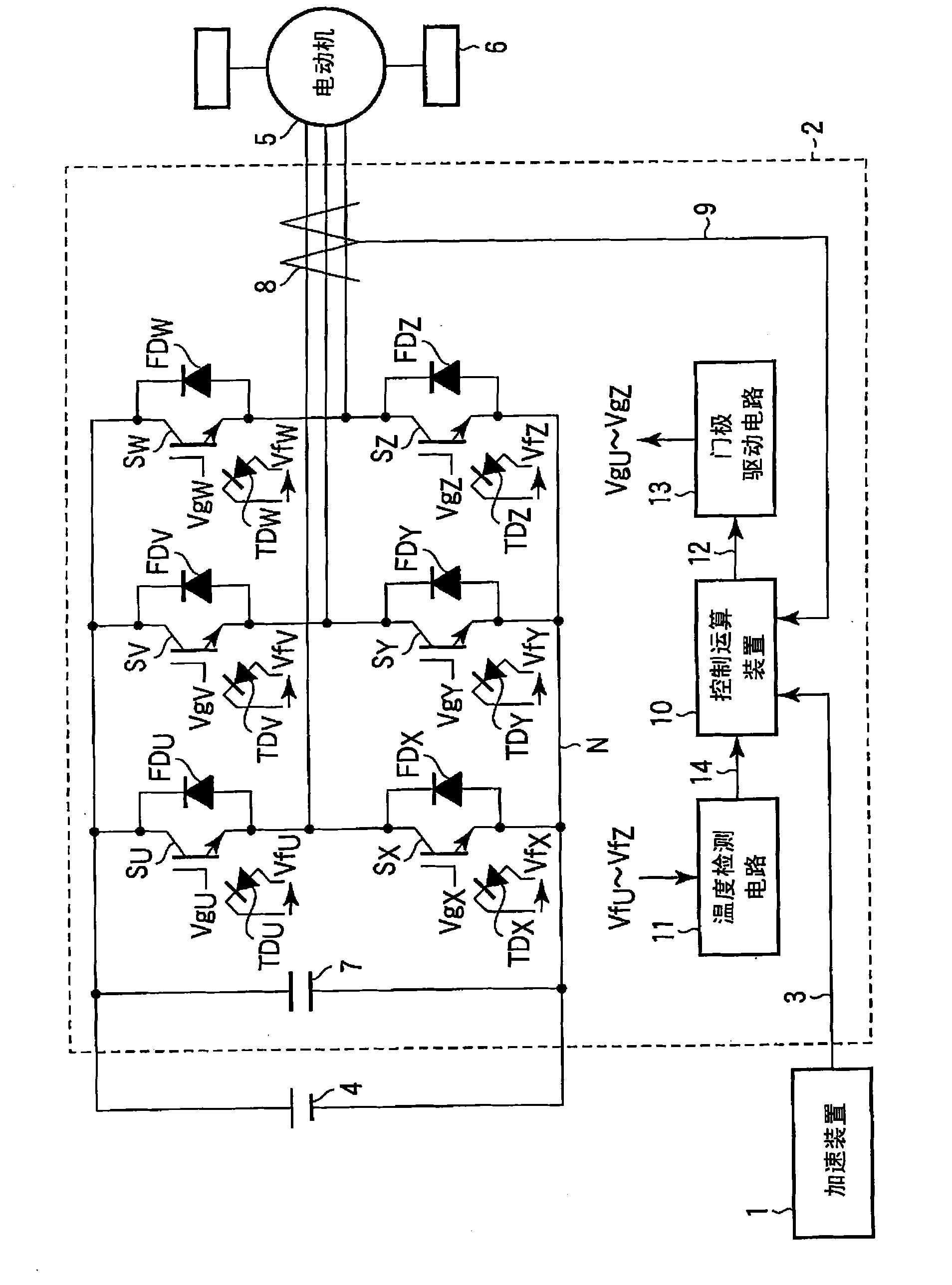
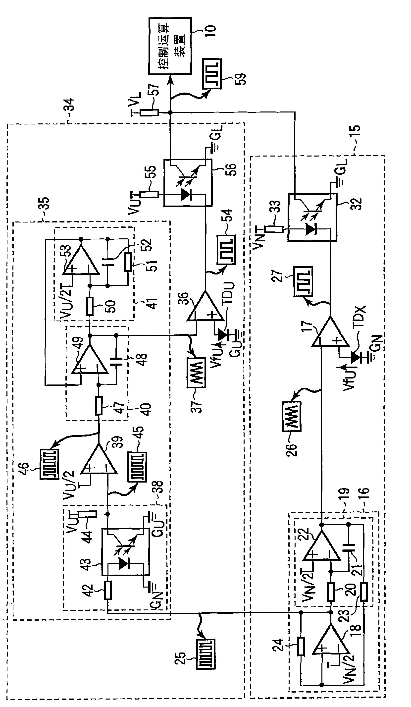
[0033] figure 2 It means measuring SW element S U , S X A diagram of the structure of the temperature detection circuit of the temperature. Temperature sensor TD U and TD X close to the SW element S U , S X Since it is provided, a voltage of several hundred V or more is applied to the SW element similarly to the SW element depending on the on / off state of the SW element. The temperature detection circuits including the temperature sensor need to be insulated from each other so as not to be destroyed even at such a high voltage.

[0034] First, explain the SW element SX The details of the temperature detection circuit 15. The temperature detection circuit 15 takes power supply voltage V N , Reference potential G N It works and includes a triangular wave generating circuit 16 and a comparator 17.

[0035] The triangular wave generating circuit 16 includes a comparator 18 and an integrating circuit 19 . The integrating circuit 19 is configured using a resistor 20 , a ...

Embodiment 2

[0053] Actually, the temperature detection accuracy of the SW element decreases due to the dispersion of the temperature sensor and the detection circuit. In this embodiment, a method for improving the temperature detection accuracy when the inverter 2 is operated will be described.

[0054] If each temperature sensor TD U ~TD Z If there is a dispersion in accuracy or the like in the temperature detection circuit, a dispersion will also occur in the relationship of "temperature / duty ratio" of the SW element. If the same "SW element temperature / duty ratio" relationship is uniformly adopted for the input PWM signals, the detection accuracy of the SW element temperature will decrease. If using respectively matched with the temperature sensor TD U ~TD Z The relationship between the SW element temperature / duty ratio can avoid the problem of dispersion, but it is necessary to determine which SW element the PWM signal of the SW element with the highest temperature input to the co...

Embodiment 3

[0057] Figure 8 This is an example in which the PWM signal of the SW element with the highest temperature is input to the control operation device 10 without synchronizing the triangular waves generated by a plurality of temperature detection circuits. In this embodiment, the measurement SW element S U , S X The case of temperature as an example.

[0058] Circuits 67 and 68 having the same configuration as the temperature detection circuit 15 described in Embodiment 1 are respectively provided in the temperature sensor TD. U 、TD X middle. The PWM signals 69 , 70 isolated from the high voltage side are input to the data selector 71 . The PWM signal 69 is input to an inverting input terminal of the comparator 74 through an RC filter composed of a resistor 72 and a capacitor 73 . Similarly, the PWM signal 70 is input to a non-inverting input terminal of the comparator 74 through a filter of a resistor 75 and a capacitor 76 . The time constant of the filter circuit is set ...


PUM


Abstract

Provided is a temperature detecting circuit which suppresses cost increase at minimum by adding a small number of components and meets requirements of insulation and high response. The temperature detecting circuit (15) outputs a first PWM signal, which corresponds to the temperature of a first temperature sensor (TDX), as a signal insulated from the first temperature sensor (TDX) from a photo interrupter (32). A temperature detecting circuit section (34) outputs a second PWM signal, which corresponds to the temperature of a second temperature sensor (TDU), as a signal insulated from the second temperature sensor (TDU) from a photo interrupter (56). A processing device (10) calculates a higher temperature of the temperatures detected by the first and the second temperature sensors (TDU, TDX), based on the PWM signal outputted from the photo interrupters (32, 56).

Description

technical field [0001] The present invention relates to a temperature detection circuit, and in particular to temperature detection of switching elements constituting an inverter device. Background technique [0002] An electric motor is used as a power source of a hybrid vehicle or an electric vehicle combined with an engine. When driving a motor, an inverter is used to obtain a predetermined torque and frequency. Inverters are installed in automobiles, and miniaturization and high power are required to ensure passenger space. [0003] The operating temperature of the inverter greatly fluctuates depending on the driving environment of the vehicle. In particular, in a hybrid vehicle in which the inverter is mounted in the engine compartment, the inverter becomes high in temperature due to the influence of heat generated by the engine. The temperature of the switching element (hereinafter referred to as SW element) in the inverter is increased due to the constant loss cause...

Claims


Application Information

Patent Timeline
Patent Type & Authority Applications(China)
IPC IPC(8): G01K7/00B60L3/00H02M7/48
CPCG01K3/005G01K7/01G01K2219/00H02M7/5387H02M2001/327H02M1/32H02M1/327
Inventor 长谷川隆太森川龙一田多伸光平田雅己
Owner KK TOSHIBA
Why Eureka
Try Eureka