Vacuum electron beam brazed joint method of tungsten/low activation steel

A vacuum electron beam, low activation steel technology, applied in welding/welding/cutting items, welding equipment, manufacturing tools, etc., can solve problems such as large thermal stress, long welding time, and inability to accurately control energy input, and achieve high efficiency , combined with the perfect effect

Inactive Publication Date: 2011-04-06
UNIV OF SCI & TECH BEIJING
View PDF5 Cites 24 Cited by
  • Summary
  • Abstract
  • Description
  • Claims
  • Application Information

AI Technical Summary

Problems solved by technology

At present, the brazing of tungsten and steel is mainly vacuum furnace brazing, the overall heating, long welding time, easy to ca

Method used


Image

  • Vacuum electron beam brazed joint method of tungsten/low activation steel
  • Vacuum electron beam brazed joint method of tungsten/low activation steel
  • Vacuum electron beam brazed joint method of tungsten/low activation steel

Examples


Embodiment 1

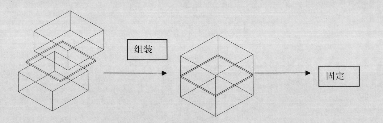
[0020] The tungsten used for brazing is a commercially available 5mm thick rolled tungsten plate, and the low activation steel is the CNSI low activation steel (9Cr2W) developed by our research group. The sample size is 10mm×8mm. Before brazing, use No. 150, No. 400, No. 600 and No. 800 sandpaper to grind the welded surface of the test piece step by step, and then use acetone to degrease the brazed surface, clean it ultrasonically with absolute ethanol, and dehydrate and dry it.

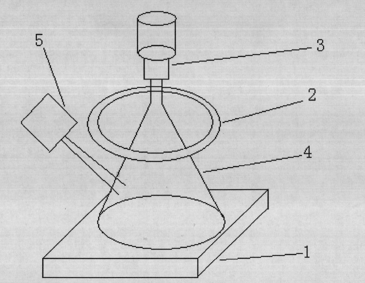
[0021] After placing the tungsten / brazing material / steel in the order from top to bottom, put them into a vacuum electron beam brazing furnace for welding. The process parameters are acceleration voltage 150kV, focusing current I f =402mA, electron beam current is I b =2mA, heating time t is 3min.

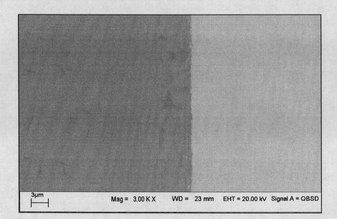
[0022] image 3 The SEM of the vacuum electron beam brazing sample is given, it can be seen that the interface is well bonded, and no large holes and cracks appear.

Embodiment 2

[0024] The tungsten used for brazing is a commercially available 5 mm thick rolled tungsten plate, and the low-activation steel is the CNSI low-activation steel (9Cr2W) developed by our research group. The sample size is 15mm×15mm. Before brazing, use No. 150, No. 400, No. 600 and No. 800 sandpaper to grind the welded surface of the test piece step by step, and then use acetone to degrease the brazed surface, clean it ultrasonically with absolute ethanol, and dehydrate and dry it.

[0025] After placing the tungsten / brazing material / steel in the order from top to bottom, put them into a vacuum electron beam brazing furnace for welding. The process parameters are acceleration voltage 150kV, focusing current I f =410mA, electron beam current is I b =2mA, heating time t is 3min.

[0026] Figure 4 The SEM of the vacuum electron beam brazing sample is given, it can be seen that the interface is well bonded, and no large holes and cracks appear.


PUM


Abstract

The invention discloses a vacuum electron beam brazed joint method of tungsten/low activation steel, belonging to the field of metal materials. According to the method, with an amorphous state T-based belt as brazing filler metal, the tungsten and the low activation steel are subjected to the brazed joint by using the vacuum electron beam braze technology wherein the amorphous state T-based belt contains 30-50 percent by weight of Ti, 30-50 percent by weight of Zr, 10-15 percent by weight of Cu and 5-10 percent by weight of Ni. During soldering, the scanning and the heating are carried out on the electron beam surface from the surface of the tungsten under the conditions that the temperature is controlled to 800-1,200DEG C, the work vacuum degree in the chamber is 1.0-5.0*10<-3>Pa, the accelerating voltage is 100-150KV, the focusing current is 100-600mA, the electron beam current is 1-10mA and the scanning frequency is 0.1-1KHz. The coil is scanned at high frequency by controlling through a computer and the heating time is 1-5 minutes. By using the method, the tungsten and the low activation steel are connected in a short time with high efficiency; and the weld seam interface can be better combined and has no defects of pore, inclusion, cracks and the like. The invention can be widely applied to connecting components of a helium cooled partial filter in a magnetic-confinement nuclear fusion experimental device.

Description

technical field [0001] The invention belongs to metal materials, and in particular relates to a method for connecting high-melting-point metal tungsten and low-activation steel. Specifically, an amorphous Ti-based foil strip is used as solder, and vacuum electron beam brazing technology is used to connect tungsten and low-activation steel. Background technique [0002] The divertor is a crucial part of modern magnetic confinement nuclear fusion devices, and it is the transition region that forms the direct contact between high-temperature plasma and materials: one side is the plasma with a temperature of several hundred million degrees, and the other side is the usual solid material. The main function of the divertor is to effectively shield the impurities from the wall, reduce the pollution of the central plasma, and discharge the particle flow and heat flow from the central plasma and the helium ash produced during the nuclear fusion reaction. At present, the international...

Claims


Application Information

Patent Timeline
IPC IPC(8): B23K1/005B23K1/20B23K103/18
Inventor 燕青芝郭双全葛昌纯
Owner UNIV OF SCI & TECH BEIJING
Why Eureka
Try Eureka