
Bipolar plate capable of doing work on double surfaces and high-energy battery thereof

A bipolar plate, one side of the substrate technology, applied in the direction of secondary batteries, lead-acid batteries, battery components, etc., can solve problems such as sulfation of the electrode surface, corrosion of the grid, and large room for battery capacity improvement

Inactive Publication Date: 2011-04-06
夏振明
View PDF3 Cites 25 Cited by
  • Summary
  • Abstract
  • Description
  • Claims
  • Application Information

AI Technical Summary

Problems solved by technology

[0010] The main reasons why the existing bipolar plate lead-acid batteries are not practical are as follows: the first is the sealing problem between the battery cells, the second is the grid corrosion problem, the third is the electrode surface sulfation problem, and the fourth is the positive and negative activity. The problem of the binding force between the material layer and the organic substrate
[0011] In addition, the existing lead-acid batteries with bipolar plates can only work on one side. If work is done on both sides, there is a lot of room for battery capacity improvement.

Method used


Image

  • Bipolar plate capable of doing work on double surfaces and high-energy battery thereof
  • Bipolar plate capable of doing work on double surfaces and high-energy battery thereof
  • Bipolar plate capable of doing work on double surfaces and high-energy battery thereof

Examples


Embodiment 1

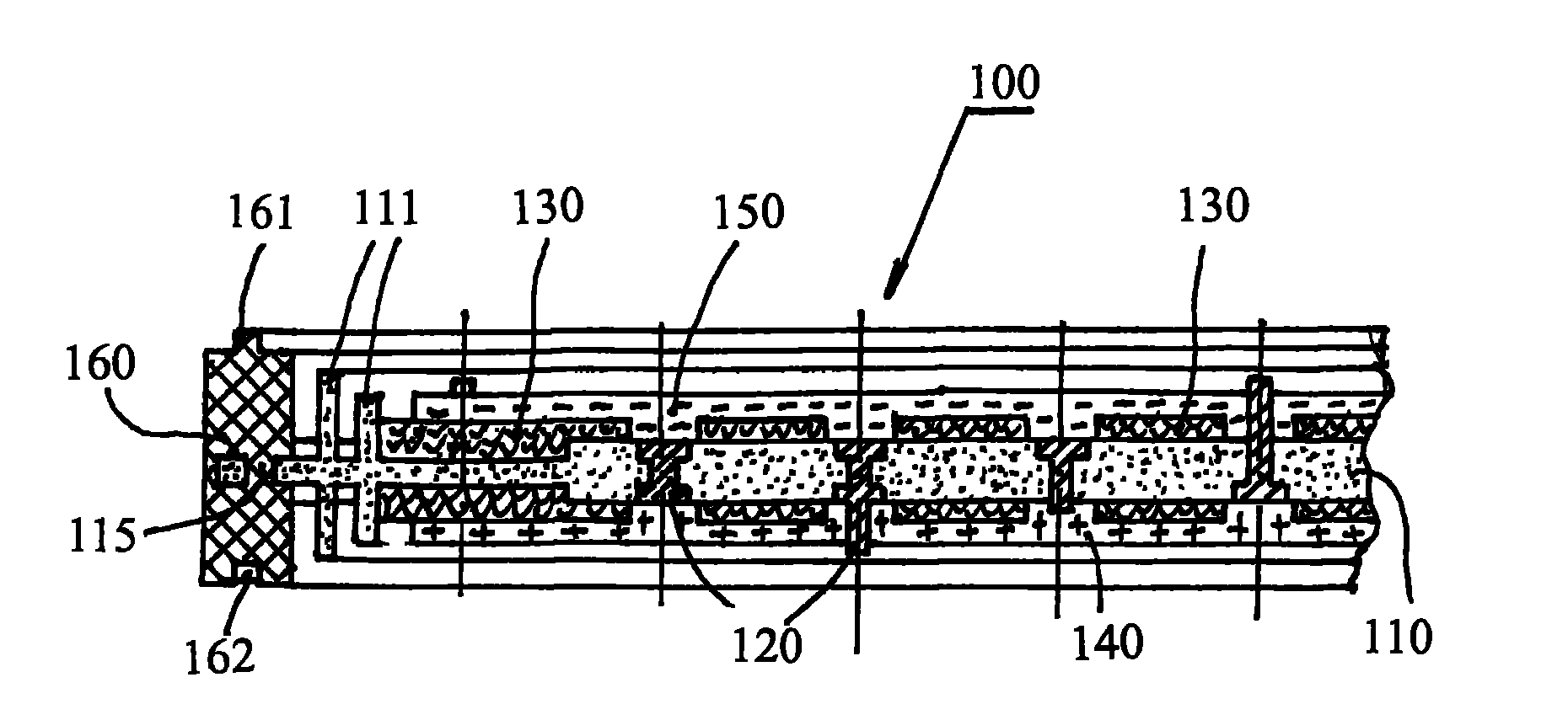
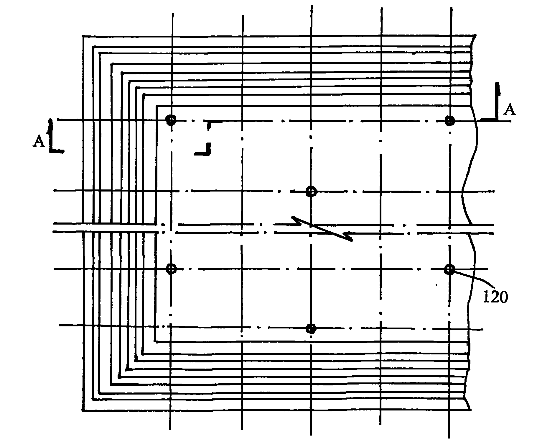
[0053] Example 1: Bipolar plate (100).

[0054] see picture 1, figure 2 , the bipolar plate (100) consists of a substrate (110), a conductive needle (120), a felt film layer (130), a positive electrode active material layer (140), a negative electrode active material layer (150), a retaining ring (111) and a frame ( 160) composition. according to Figure 7 , Figure 8 , Figure 9 , Figure 10 , Figure 11 , Figure 12 , Figure 13 , Figure 14 Shown, preferred pure lead is made into the conductive pin (120) of different shapes, or makes the conductive pin (120) of one or more shapes in them, then the conductive pin (120) is pressed Figure 15A , Figure 15B , Figure 15C , Figure 15D , Figure 15E The upper coating film (125) is shown, and the coating film (125) is preferably made of a hydrophobic material, and more preferably made of the same fluoropolymer as that of the substrate (110). Put the conductive needles (120) coated with the coating film (125) into the...

Embodiment 2

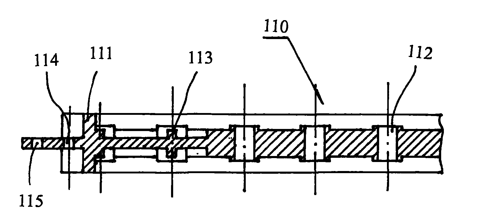
[0055] Embodiment 2: The second form of the substrate (110).

[0056] See Figure 3, Figure 4 , the base plate (110) is provided with: a retaining ring (111), a chamfer (116) is arranged on the side of the retaining ring (111), and a vent hole (114) is arranged on the chamfer (116), the vent hole (114) The air chambers of each battery unit are connected to form a common air chamber, so that the pressure difference of each battery unit is 0, and the air hole (114) can also be used as the inlet and outlet of the electrolyte; The hole platform (112) used for the needle (120), the conductive needle (120) coated with the coating film (125) can be inserted into the hole platform (112) and fixed on it, the fixing method can be welding, heat welding, adhesive bonding In order to enhance the strength of the substrate (110) and produce a large-scale battery, a large number of reinforcing ribs (113) are arranged on the substrate (110), and the reinforcing ribs (113) and the hole platfor...

Embodiment 3

[0057] Embodiment 3: Electrode modification and anticorrosion treatment of the conductive needle (120).

[0058] In a lead-acid battery, if the conductive pins (120) are made of titanium, stainless steel, or non-preferred metal materials, electrode modification is preferably performed. The formed conductive needle (120) is coated with an inorganic conductive material such as conductive ceramics, conductive glass or conductive oxide as a whole or part of the contact electrolyte, and the preferred material is (SnO 2 +Sb 2 o 3 ), (SnO 2 +SbO×+IrO 3 ), Ti 3 SiC 2 、Ti 3 AiC 2 、TiB 2 , TiC; and then coat a layer of organic conductive coating on the outside of the inorganic layer by means of electrode modification. The preferred material is polyphenylamine PAn conductive high polymer or PAn composite conductive plastic with other materials. This modification method can also be non-preferably coated with only one inorganic conductive layer or only coated with one organic cond...


PUM


Abstract

The invention relates to a bipolar battery used for an electric vehicle, in particular to a bipolar plate lead-acid battery, which solves the problems that battery cells of the traditional bipolar battery cannot be sealed and the bipolar plate does work on a single surface. In the invention, a hydrophobic material is utilized as a substrate, a conductive needle is embedded in the substrate, blanket film layers are added on two surfaces of the substrate, a positive and negative active substance layers are respectively coated outside the blanket film layers to form a bipolar plate, a common air chamber is arranged in the bipolar battery formed by the bipolar plate and provided with a pressure reducing valve. The structure ensures that the battery does not has short circuit and can still work normally when the battery cells in the battery are not in a sealed state, thereby paving a way for commercial application of the bipolar battery; moreover, because the bipolar plate in the battery does work on double surfaces, the bipolar battery capacity is improved by more than 30%, the gravimetric specific energy of the bipolar plate lead-acid battery can exceed 80Wh / kg which approaches to the level of a lithium battery but the cost of the bipolar plate lead-acid battery is less than one quarter of that of a lithium battery; and the bipolar battery can work when the internal pressure of the battery is below 30kPa, and is sealed and environmentally-friendly in use. The invention provides the bipolar plate capable of doing work on double surfaces and a high energy battery thereof.

Description

Technical field: [0001] The invention relates to a high-energy storage battery, especially a lead-acid battery, which is mainly used as a power source for electric vehicles such as electric vehicles, electric bicycles, and electric motorcycles. Background technique: [0002] In order to improve the capacity and life of lead-acid batteries, compared with ordinary lead-acid batteries, people have developed second-generation new products such as light grid lead-acid batteries, wound lead-acid batteries and bipolar plate lead-acid batteries. In the area of ​​lightweight grid lead-acid batteries, attempts to replace lead or lead alloy grids with plastic grids or titanium wire grids have been unsuccessful. Small-capacity batteries have been well used in the field of wound lead-acid batteries, but large-capacity batteries are huge in size and are not suitable for application in electric vehicles. In the field of bipolar plate lead-acid batteries, batteries made of metal raw materi...

Claims


Application Information

Patent Timeline
IPC IPC(8): H01M4/14H01M10/06H01M2/12H01M10/50H01M2/14
CPCY02E60/126Y02T10/7016Y02E60/10
Inventor 夏振明
Owner 夏振明
Learn More