Design method capable of using external synchronous for cameral with various data output formats

An output format and camera technology, applied in the direction of image communication, color TV parts, TV system parts, etc., can solve the problems of lack of output in multiple data formats, affecting the quality of original data, and single output signal, etc., to achieve The effect of easy interface of external equipment, less program running time, and quick programming

Active Publication Date: 2011-04-06
WISESOFT CO LTD
View PDF4 Cites 17 Cited by
  • Summary
  • Abstract
  • Description
  • Claims
  • Application Information

AI Technical Summary

Problems solved by technology

[0002] Existing cameras, the data output format is single, no external synchronization is used, and there is no output of multiple data formats
In this way, when synchronization with external events is required, synchronization with external events cannot be achieved
At the same time, due to the single output signal, when an external device needs to perform digital image processing, an external device must be used to convert the data format, which not only affects the quality of the original data, but also takes up the processing time of the external device.

Method used


Image

  • Design method capable of using external synchronous for cameral with various data output formats
  • Design method capable of using external synchronous for cameral with various data output formats
  • Design method capable of using external synchronous for cameral with various data output formats

Examples


Embodiment 2

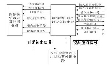
[0032] Embodiment 2, see attached image 3. On the basis of Embodiment 1, a video compression processing chip and its peripheral circuits are added. Adding a video compression processing chip can be a dedicated compression integrated circuit or a digital signal processing (DSP) chip. This example uses the TE3310 chip of TOKYO Company.

[0033] The programmable logic gate array receives the brightness signal of the pixels of the imaging plane output by the image sensor. Perform Bayer transformation to generate RGB format video signal, and then convert RGB format video signal to YUV format video signal. The programmable logic gate array outputs the video output signal (RGB signal or YUV signal) to the video compression processing chip, and the video compression processing chip completes M-JPEG compression or H264 compression, and sends the compressed data to the programmable logic gate array FPGA.

Embodiment 3

[0034] Embodiment 3, see attached Figure 4 . On the basis of Embodiment 1, an embedded processing chip and a peripheral circuit interface module are added. The added embedded processing chip can be an ARM chip or a POWER PC chip. What this example uses is the AR91RM9200 chip of Atmel Company. The high-speed serial interface, parallel interface, and low-voltage differential signal interface in the external communication interface are connected to the programmable gate array module, and the two-way communication of the above-mentioned interfaces is realized by the programmable gate array module FPGA. The network interface is connected to the embedded chip, and the embedded chip completes the network communication. The communication between the embedded chip and the programmable gate array module FPGA is completed through the parallel interface on the board. The programmable logic gate array receives the brightness signal of the pixels of the imaging plane output by the imag...

Embodiment 4

[0035] Embodiment 4, see attached Figure 5 . On the basis of Embodiment 1, a video compression processing chip and its peripheral circuits, an embedded processing chip and a peripheral circuit interface module are added. Like Embodiment 3, the high-speed serial interface, parallel interface, and low-voltage differential signal interface in the external communication interface are connected to the programmable gate array module, and the bidirectional communication of the above-mentioned interfaces is realized by the programmable gate array module FPGA. The network interface is connected to the embedded chip, and the embedded chip completes the network communication. The communication between the embedded chip and the programmable gate array module FPGA is completed through the parallel interface on the board.

[0036] The programmable logic gate array receives the brightness signal of the pixels of the imaging plane output by the image sensor. Perform Bayer transformation t...


PUM


Abstract

The design method capable of using external synchronous for a camera with various data output formats, relating to data output of the camera. A transformation between an external synchronizing signal and a CCD (charge coupled device) time sequence is carried out by utilizing a programmable gate array module, so as to realize two-way communication with the external synchronization. A synchronizing signal is transmitted by externally connecting an input line module, an input field module, an input clock module and an input exposure module on FPGA (filed programmable gate array), and the two-way communication with the external synchronization is realized by externally connecting a circumscribed high-speed serial interface, a parallel interface, a low-voltage differential signal interface and a network interface. Software control FPGA uses an external control signal firstly. The control signal can be one or two or three or four of an input field synchronizing signal, an input line synchronizing signal, an input clock signal and an input exposure control signal. The external device can be added with a video compression chip, or an embedded chip, or both the video compression chip and the embedded chip. The invention enables the exposure time to be synchronous with a specific event, and to be synchronous with an operation processing of the external device, enables the software to program fast, and enables program running time and memory using to be less.

Description

technical field [0001] The invention belongs to the field of computer applications, and in particular relates to camera data. Background technique [0002] The existing camera has a single data output format, does not use external synchronization, and does not have output in multiple data formats. In this way, when synchronization with external events is required, synchronization with external events cannot be achieved. At the same time, due to the single output signal, when an external device needs to perform digital image processing, an external device must be used to convert the data format, which not only affects the quality of the original data, but also takes up the processing time of the external device. Contents of the invention [0003] The purpose of the present invention is to provide a design method for cameras with multiple data output formats that can be used for external synchronization. According to this method, the field synchronization and line synchron...

Claims


Application Information

Patent Timeline
Patent Type & Authority Applications(China)
IPC IPC(8): H04N5/232H04N5/235H04N5/77H04N7/26H04N19/42
Inventor 莫思特胡术冯达敏吴志红
Owner WISESOFT CO LTD
Why Eureka
Try Eureka