Eureka AIR delivers breakthrough ideas for toughest innovation challenges, trusted by R&D personnel around the world.

System and method for line scan confocal ophthalmoscope

A technology of line scanning and scanning galvanometer, which is applied in the system field of online scanning confocal ophthalmoscope, can solve the problems of complex optical path, uneven distribution of beam energy, difficult control, etc., and achieve uniform distribution of beam energy, fast image construction speed, The effect of clock synchronization convenience

Inactive Publication Date: 2011-04-13
INST OF OPTICS & ELECTRONICS - CHINESE ACAD OF SCI
View PDF7 Cites 42 Cited by
  • Summary
  • Abstract
  • Description
  • Claims
  • Application Information

AI Technical Summary

Problems solved by technology

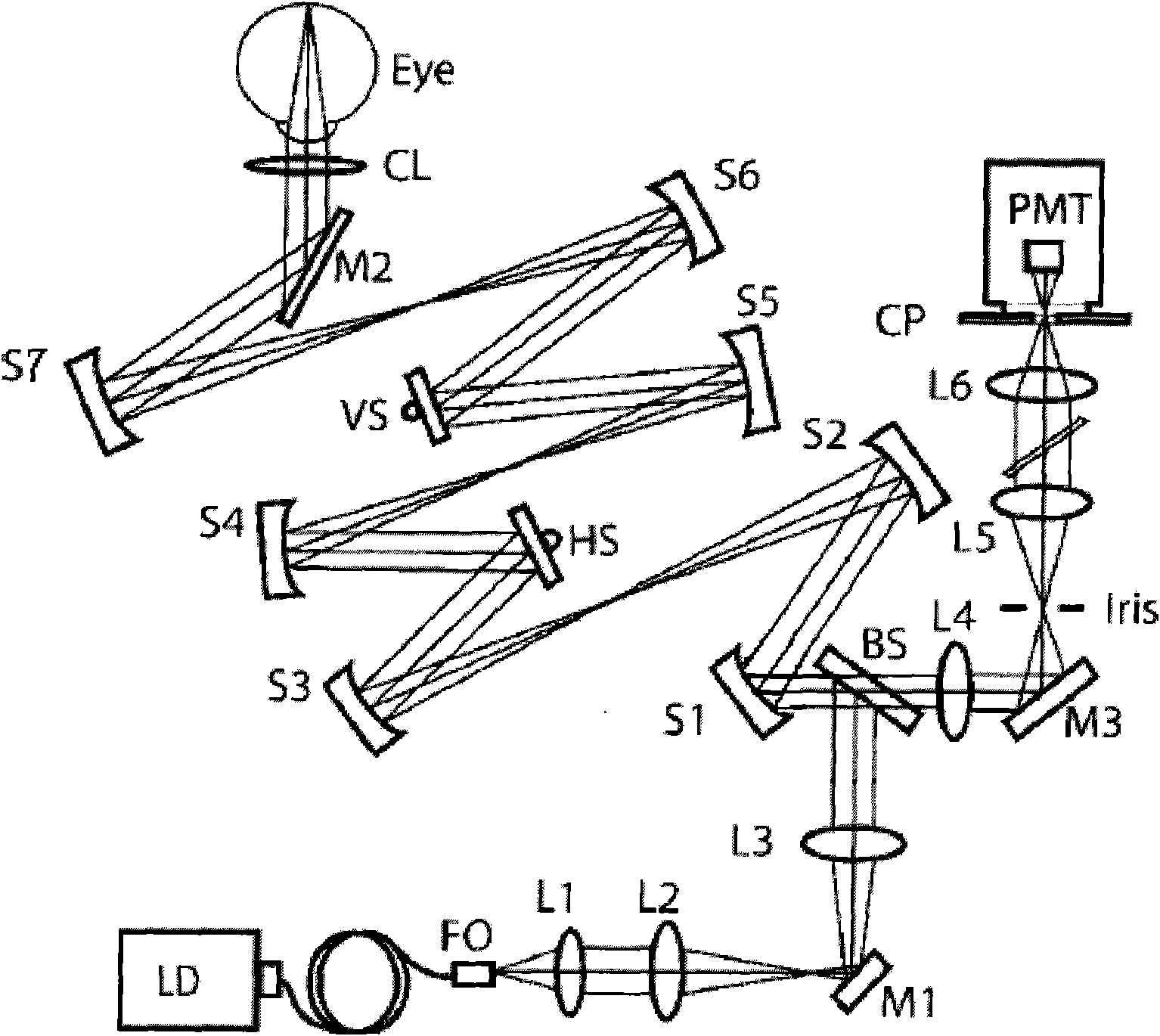
This point-scanning confocal imaging technology has good imaging effect, but it has many defects: (1) There are many optical path components, the optical path is complicated, the system structure is large, and it is inconvenient to use, so it is not suitable for widespread use; And vertical scanning VS two galvanometers, there are many moving parts, it is difficult to control; (3) The light spot energy of point scanning is small, so it needs to use photomultiplier tube PMT or other weak light spot detectors, the obtained image has low contrast, and the frame rate The speed is small (<30fps), so that the retinal jitter image of the intra-frame image cannot be eliminated; (4) the use of point scanning to image the fundus retina usually requires dilated observation and requires the observer to have a good fixation ability. Difficult for eye disease patients, the elderly and children
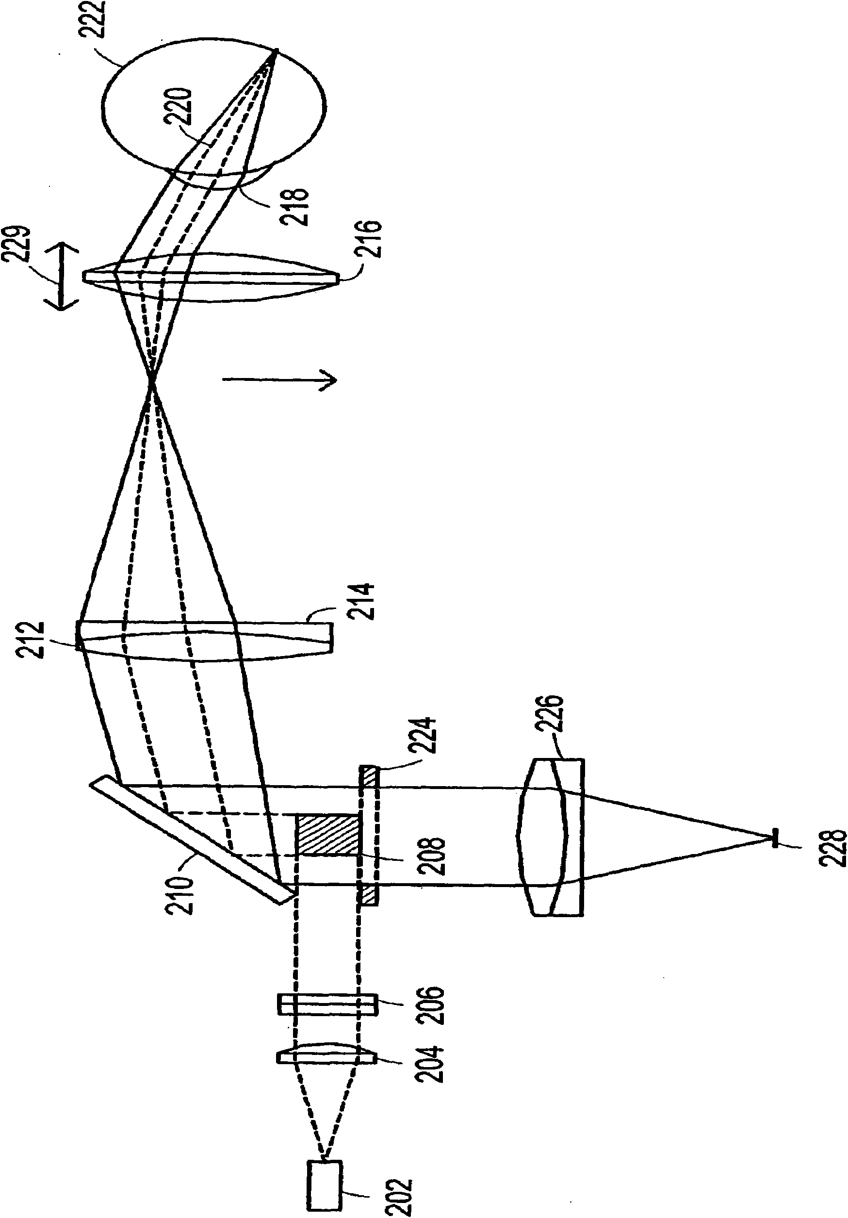
This device achieves the goal of "quasi" confocal imaging with high resolution, but it still has many defects: (1) it adopts laser point light source for illumination, the light source is complicated to adjust, and the energy distribution of the beam is uneven and Gaussian; (2) For the divergent beam of the point light source, the line beam generating device is composed of two cylindrical lenses, the structure of the line beam generating device is complex, the adjustment is difficult, and the quality of the generated line beam is not good; The energy distribution is uneven, showing a Gaussian distribution. The line beam is focused and diverged many times during the process of propagating to the fundus, and the quality of the line beam is poor; (4) The scanning beam reaching the human eye is orthogonal to the incident beam reaching the scanning galvanometer, The incident beam is scanned after being deflected by the galvanometer by 90 degrees. The scanning method is complex, difficult to control, and has low precision.

Method used


Image

  • System and method for line scan confocal ophthalmoscope
  • System and method for line scan confocal ophthalmoscope
  • System and method for line scan confocal ophthalmoscope

Examples


Embodiment Construction

[0049] Such as Figure 4 As shown, it is a structural diagram of the line scanning confocal ophthalmoscope system of the present invention. The line scanning confocal ophthalmoscope system of the present invention includes a line beam generating module 1, a spectroscopic module 2, a scanning module 3, an imaging module 5 and an output Module 6.

[0050] The line beam generating module 1 is connected to the spectroscopic module 2, and is composed of a point light source 100, a collimating beam expander 110 and a line beam intercepting device 120, and is used to generate a one-dimensional line beam from the divergent light beam of the point light source 100, and the light emitted by the point light source 100 The divergent beam is collimated by the collimating beam expander 110 and then outputs a parallel beam. The line beam intercepting device 120 intercepts the parallel beam output by the collimating beam expander 110 into a one-dimensional line beam line and sends it to the s...


PUM


Abstract

The invention relates to a system and method for a line scan confocal ophthalmoscope. The system comprises a linear light beam generation module, a splitting module, a scanning module, an imaging module and an output module. A linear light beam is subject to one-dimensional space scanning by the line scan confocal ophthalmoscope to illuminate fundus oculi retina, simultaneously a linear detector is used for image non-scan light beams reflected from the fundus oculi retina, the system only uses one scanning galvanometer and one linear detector, and the number of active members is small; and simultaneously, a confocal slit is conjugated with the plane of the fundus oculi retina, thereby eliminating the influence of eliminate stray light of a non-retina plane on imaging quality and obtaining high resolution by using the confocal imaging principle. The invention has the advantages of simple structure, short light path, good stability and high imaging frame frequency, is easy for manufacture and suitable for adjustment, and is small and exquisite.

Description

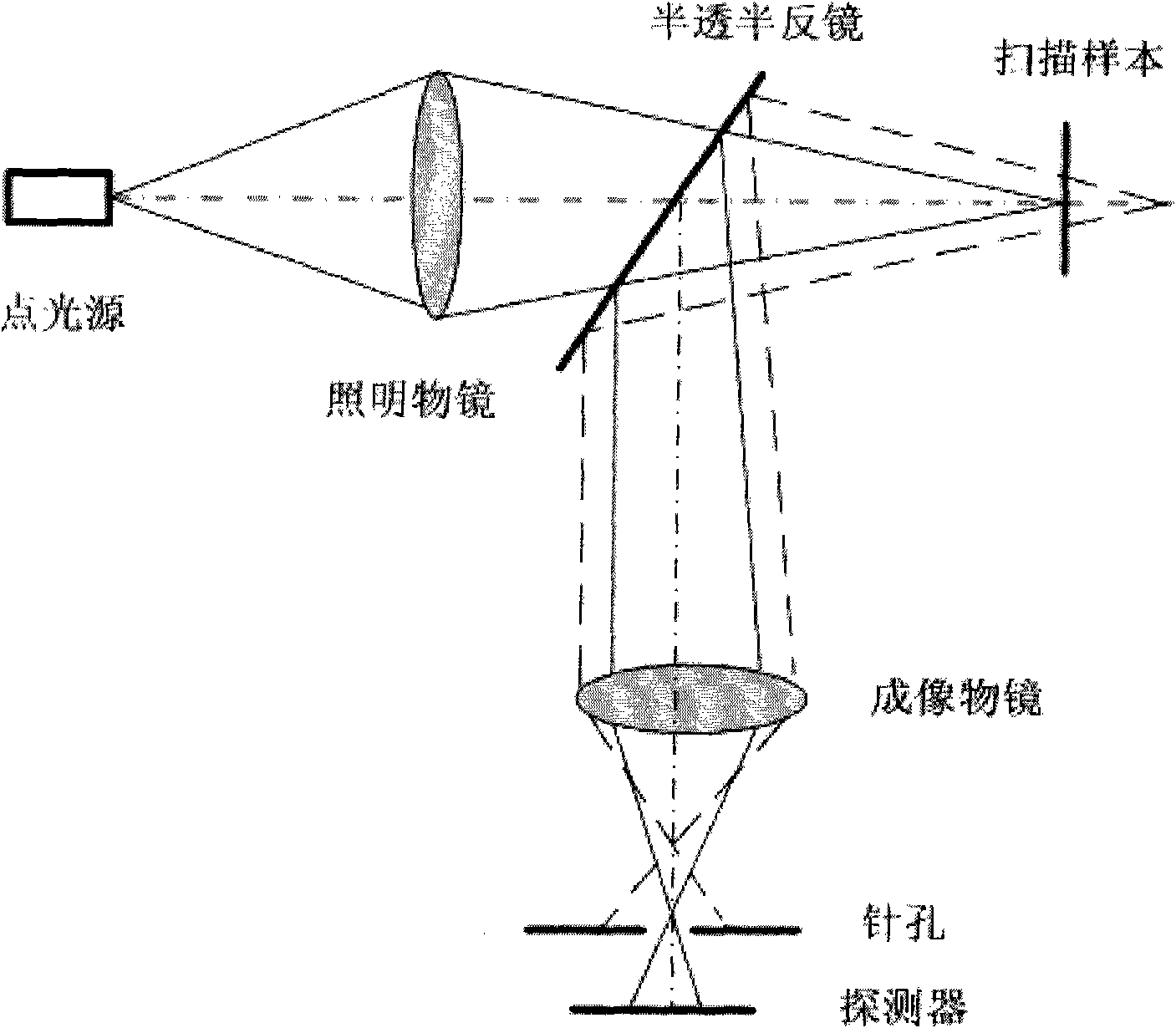
technical field [0001] The invention relates to a confocal imaging system and method in the field of optical imaging, in particular to a line scanning confocal ophthalmoscope system and method, which can be widely used in biomedical ophthalmological examination. Background technique [0002] The successful application of confocal scanning technology in imaging has broken through the bottleneck of traditional optical imaging, and can obtain high-resolution imaging, which has promoted the development of optical imaging detection technology. In recent years, scholars have conducted a lot of research on this technology, and realized a variety of confocal scanning imaging devices. [0003] The optical principle of confocal scanning technology is as follows: figure 1 As shown in , the scanning sample is at the focal plane position of the illumination objective lens, and at the same time, the detector is at the focal plane position of the imaging objective lens, that is, at the co...

Claims


Application Information

Patent Timeline
IPC IPC(8): A61B3/12A61B3/15
Inventor 史国华何益张雨东
Owner INST OF OPTICS & ELECTRONICS - CHINESE ACAD OF SCI
Why Eureka
Eureka Blog
Learn More