Hydraulic transmission device for plate shearing machine

A hydraulic transmission device, shearing machine technology, applied in the direction of shearing device, shearing machine equipment, metal processing equipment, etc., can solve the problems of small installation space, nitrogen leakage, affecting the normal use of machine tools, etc., to achieve convenient adjustment and avoid accidents Effect

Inactive Publication Date: 2011-04-13
周建波
View PDF0 Cites 14 Cited by
  • Summary
  • Abstract
  • Description
  • Claims
  • Application Information

AI Technical Summary

Problems solved by technology

[0003] The return stroke of the upper knife rest of these two kinds of shearing machines is driven by the nitrogen return cylinder with relatively high pressure to push the return stroke of the upper knife rest, but the current shearing machines have a big defect: the pressure in the nitrogen return cylinder is about 6MPa , Nitrogen leakage is unavoidable during the working process of the shearing machine. When the nitrogen leaks to a certain extent, the pressing action of the pressing cylinder and the downward movement of the upper knife rest are out of harmony, and the action of pressing the material first and then the upper knife rest cannot be realized. According to the cutting process requirements, after air leakage, even if the action is coordinated, the initial pressing force will decrease at this time, and the cut sheet will not meet the quality requirements, so it is necessary to inflate the nitrogen return cylinder, the initial pressing force, Whether it can meet the requirements can only be felt by experience, and it cannot be adjusted in real time. Frequently filling the nitrogen return cylinder seriously affects the normal use of the machine tool; it is a very dangerous process when the nitrogen return cylinder is assembled and connected with the upper tool holder. The nitrogen return cylinder Installed in the inner cavity of the upper tool holder, it is necessary to inject high-pressure nitrogen gas while holding the return cylinder by a person to calibrate the upper and lower connection points. The installation space is small and the vision is poor. When the high-pressure nitrogen gas is charged into the return cylinder, the piston rod of the return cylinder is in Under the action of high-pressure nitrogen, it is quickly pushed out, supported on the upper tool holder, and the upper tool holder is lifted upwards. If you are not careful, it will not be in place accurately, and the piston rod will often rush out of the cylinder, resulting in serious injury accidents. , such as severed hands and feet; the shearing machine works through the opening and closing of the electromagnetic overflow valve, the upper knife rest cuts down to the end of the stroke, and the electrical control sends a signal to open the electromagnetic overflow valve and upper the knife The return trip of the rack, the return trip must return to the top dead center to stop, and it cannot be stopped at any position, which is not conducive to the inspection and adjustment of the uniformity of the blade gap. After the adjustment of the uniformity is completed, if you forget to close the ball valve, the ball valve is in a closed state. Working machine tools can easily cause serious equipment accidents

Method used


Image

  • Hydraulic transmission device for plate shearing machine
  • Hydraulic transmission device for plate shearing machine
  • Hydraulic transmission device for plate shearing machine

Examples


specific Embodiment approach 1

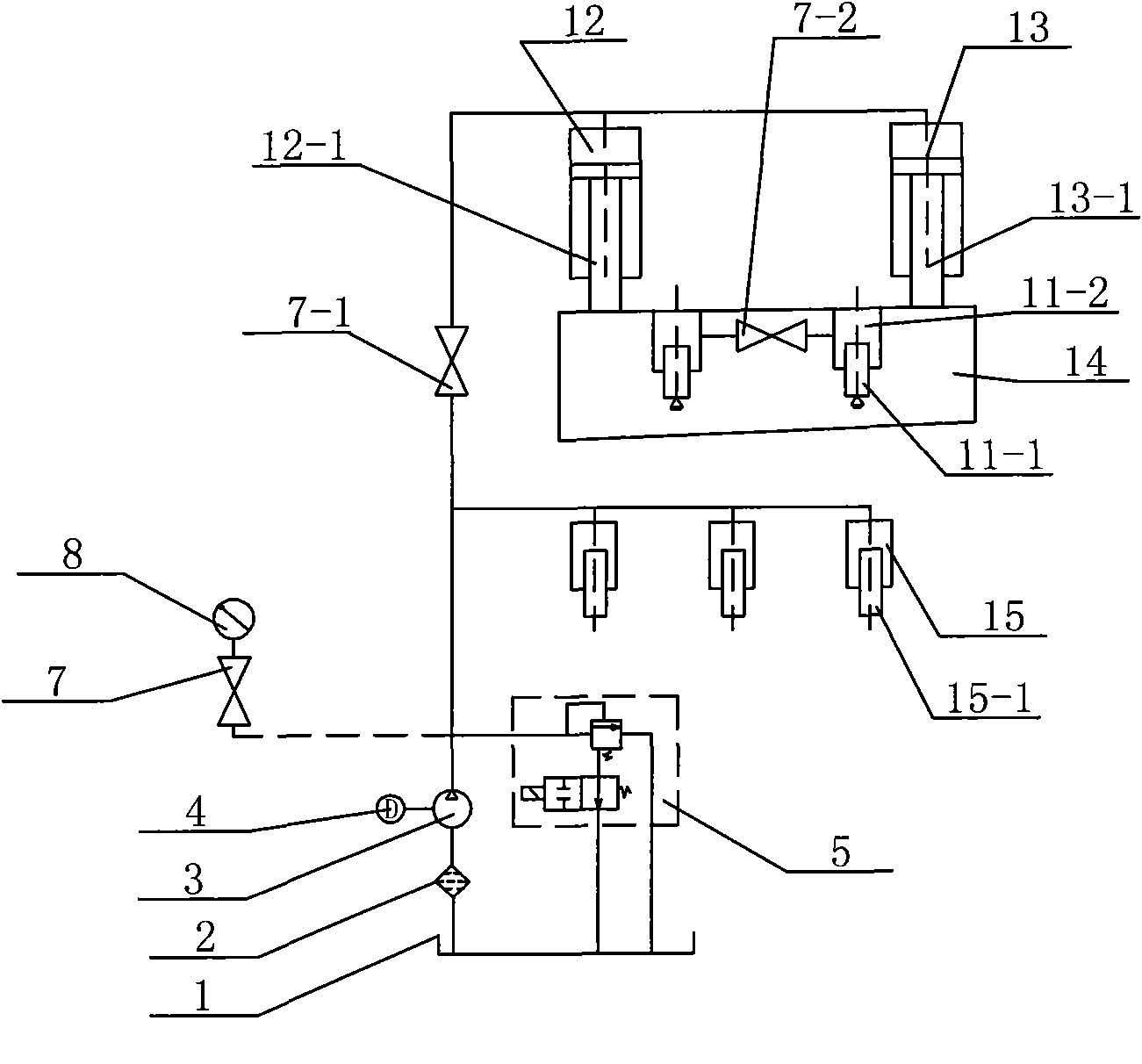
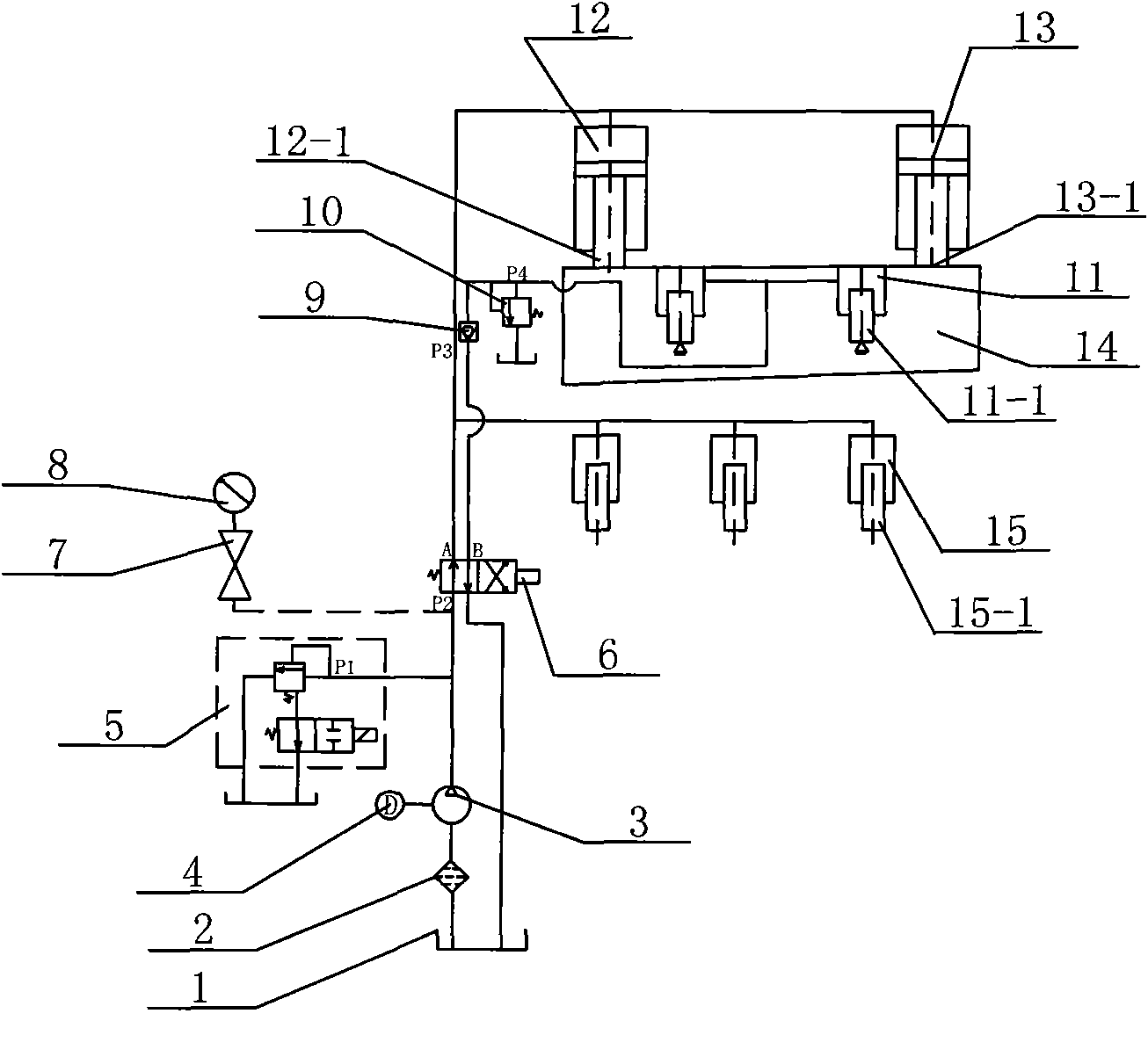
[0021] Specific implementation mode 1: refer to image 3 , Figure 8-9 , this specific embodiment adopts the following technical scheme: it comprises an oil tank 1, an oil suction filter 2, a hydraulic oil pump 3, an electric motor 4, an electromagnetic relief valve 5, a reversing valve 6, a pressure gauge switch 7, a pressure gauge 8, a one-way valve 9. Pressure regulating valve 10, left main oil cylinder 12, right main oil cylinder 13, upper tool holder 14, pressing oil cylinder 15, it also includes hydraulic return cylinder 11, oil tank 1 is connected with hydraulic oil pump 3 through oil suction filter 2, electric motor 4 It is connected with the hydraulic oil pump 3, the electromagnetic relief valve 5 is arranged between the hydraulic oil pump 3 and the reversing valve 6, the pressure gauge 8 is connected with the pressure gauge switch 7, and the reversing valve 6 is connected with the left main oil cylinder 12, the right main oil cylinder 13 and The pressing oil cylinde...

specific Embodiment approach 2

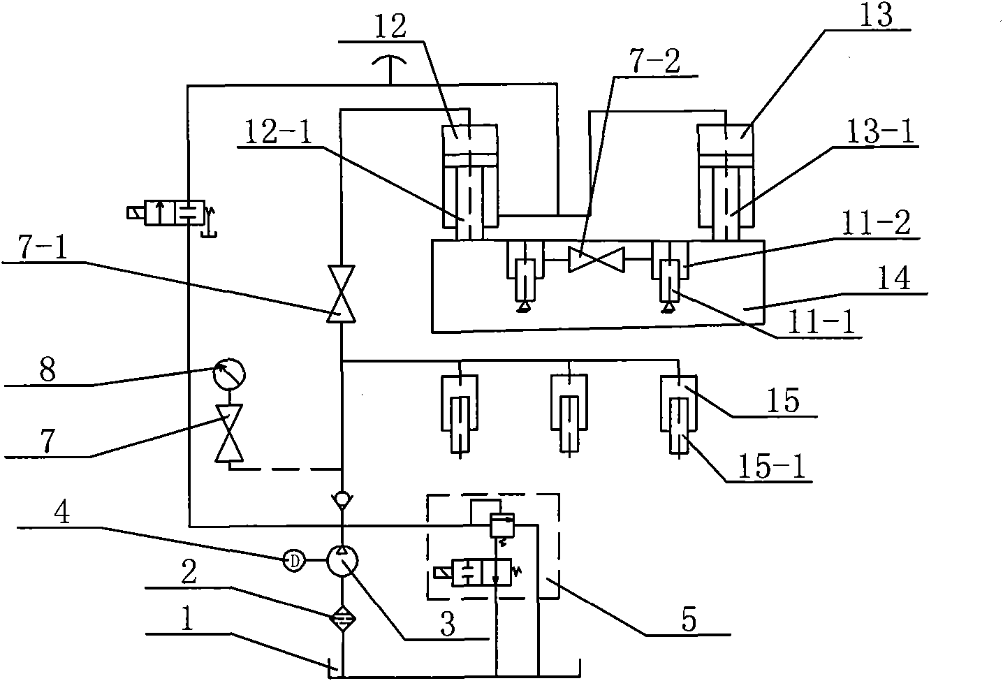
[0028] Specific implementation two: refer to Figure 4 , Figure 10-11 The difference between this specific embodiment and the specific embodiment 1 is that the left hydraulic oil tank 12 and the right hydraulic oil tank 13 are connected in series.

specific Embodiment approach 3

[0029] Specific implementation mode three: refer to Figure 5-6 The difference between this specific embodiment and the specific embodiments 1 and 2 is that the electromagnetic relief valve 5 is arranged above the reversing valve 6 , and one end of the pressing oil cylinder 15 is connected to the electromagnetic relief valve 5 .

[0030]The oil outlet of the hydraulic oil pump 3 is connected to the P2 port of the reversing valve 6, the oil outlet A of the reversing valve 6 is connected to the oil inlet P1 port of the electromagnetic relief valve 5, the left main oil cylinder 12, the right main oil The oil cylinder 13 is connected with the pressing oil cylinder 15, the oil outlet B of the reversing valve 6 is connected with the straight direction port P3 of the check valve 9, and the other port of the check valve 9 is connected with the P4 port of the pressure regulating valve 10 and the hydraulic pressure. The oil inlet of the return cylinder 11 is connected.

[0031] During ...


PUM


Abstract

The invention provides a hydraulic transmission device for a plate shearing machine, and relates to a plate shearing machine used in a forging and pressing product. In the invention, an oil outlet of a hydraulic pump (3) is connected with an oil inlet P1 of an electromagnetic relief valve (5) and an oil inlet P2 of a reversing valve (6); an oil outlet A of the reversing valve (6) is connected with a left master cylinder (12), a right master cylinder (13) and a material pressing cylinder (15); an oil outlet B of the reversing valve (6) is connected with a straight-through opening P3 of a one-way valve (9); and the other opening of the one-way valve (9) is connected with an opening P4 of a pressure regulating valve (10) and an oil inlet of a hydraulic return cylinder (11). By adopting the hydraulic transmission device, an upper knife rest can stop at any position, thus greatly facilitating adjustment on clearance uniformity degree of a knife blade, avoiding accidents and being safer and more convenient.

Description

Technical field: [0001] The invention relates to a hydraulic shearing machine and a hydraulic shearing machine in forging products, in particular to a hydraulic transmission device of the shearing machine. Background technique: [0002] The shearing machine in the prior art is mainly driven by parallel oil cylinders to drive the working movement of the tool rest and serial oil cylinders to drive the working movement of the tool rest, and the nitrogen return cylinder drives the return movement of the tool rest. like Figure 1-2 As shown, the operation of the electric motor 4 drives the hydraulic oil pump 3 to operate, and the hydraulic oil output by the hydraulic oil pump 3 is unloaded through the electromagnetic relief valve 5 (the electromagnetic valve is open at this time), and the hydraulic oil flows back to the oil tank 1. At this time, the upper part of the shearing machine is The tool holder 14 does not move, when the solenoid valve of the electromagnetic relief valve ...

Claims


Application Information

Patent Timeline
Patent Type & Authority Applications(China)
IPC IPC(8): B23D15/14B23D15/08
Inventor 周建波周霆
Owner 周建波
Why Eureka
Try Eureka