
Full-position welding method for pipeline by full-automatic external welding machine

A welding method and fully automatic technology, applied in welding equipment, arc welding equipment, manufacturing tools, etc., can solve the problems of incompatibility of root welding speed and cover welding speed, difficulty in on-site maintenance, high automatic welding efficiency, and reduce welding speed. Seam metal filling amount to ensure effective protection and improve efficiency

Active Publication Date: 2011-04-13
BC P INC CHINA NAT PETROLEUM CORP +1
View PDF2 Cites 30 Cited by
  • Summary
  • Abstract
  • Description
  • Claims
  • Application Information

AI Technical Summary

Problems solved by technology

[0003]At present, the pipeline automatic welding process used in domestic pipeline all-position welding can be roughly divided into three categories: the first category is gas shielded semi-automatic root welding + automatic external welding The filling and capping process of the welding machine only realizes automatic welding in the filling layer welding and capping layer welding. It has become a bottleneck restricting automatic welding construction; the second category is the automatic root welding + automatic external welding machine capping process of the pipeline external welding machine; the third category is the automatic root welding + automatic external welding machine capping process of the pipeline internal welding machine
This technology has the fastest welding speed and the best quality, but the cost of equipment is very high, and the structure is complicated, making it difficult to maintain on site.

Method used


Image

  • Full-position welding method for pipeline by full-automatic external welding machine
  • Full-position welding method for pipeline by full-automatic external welding machine

Examples


Embodiment Construction

[0019] The present invention is not limited by the following examples, and the specific implementation manner can be determined according to the above-mentioned technical solutions and actual conditions of the present invention.

[0020] Below in conjunction with preferred embodiment the present invention is further discussed:

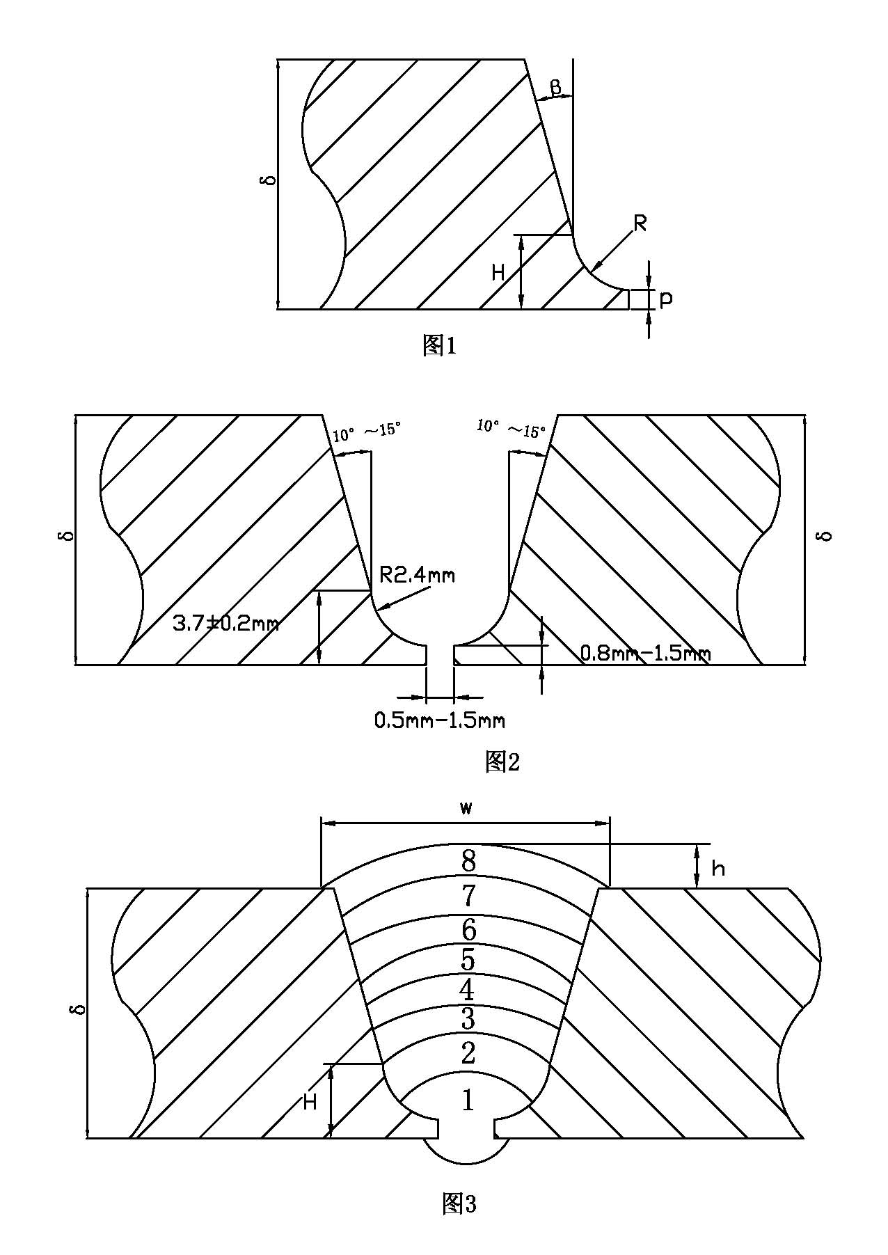
[0021] 1. Processing groove. The material of the steel pipe is X80 steel, the pipe diameter is ¢1219×18.4mm, the shape of the groove is U-shaped groove with blunt edge, and the groove machine is used for processing, such as figure 1 As shown, the upper groove angle β is 10°~15°, the height H between the inflection point of the variable groove and the inner wall is 3.7±0.2mm, the arc radius R is 2.4mm, and the blunt edge p is 0.8mm~1.5mm. All pipe end bevels must be processed by mechanical methods, and the processed bevel end faces must be flat, uniform and smooth.

[0022] During the welding process, although the torch swing frequency and le...


PUM


Abstract

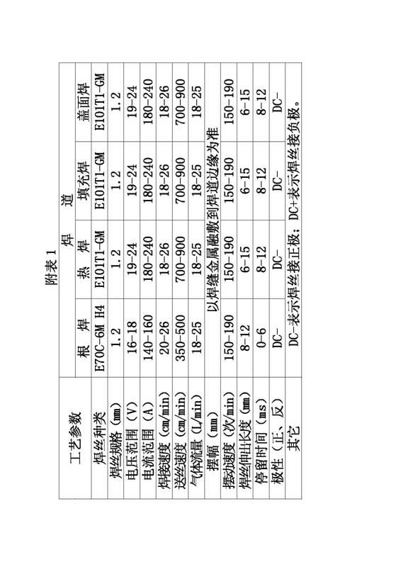
The invention discloses a full-position welding method for a pipeline by a full-automatic external welding machine, which comprises the following steps of: pretreating a pipe orifice end face of the pipeline; conventionally checking a welded pipeline, and performing environmental protection and equipment debugging; inputting and saving welding technical parameters into a tractor controller of an automatic external welding machine; machining the pipe orifice end face of the pipeline to be welded to form the needed groove by using a groove processing machine, and clearing and assembling the pipe orifice end face with the machined groove; checking welding rails and loading a welding tractor; and performing pre-welding preheating on the pipeline to be welded according to regulation requirement in welding technology, and welding according to the specified welding technical parameters. The method realizes real full-automatic pipeline welding, guarantees stable control of the welding process, ensures effective protection on electric arcs and molten baths, guarantees impact toughness of welded joints and welding quality, solves the bottleneck problems which restrict semi-automatic welding flow construction work, and improves the working efficiency.

Description

technical field [0001] The invention relates to the technical field of welding of long-distance pipelines, and relates to an all-position full-automatic external welding machine welding method for pipelines. Background technique [0002] The full-automatic welding of all positions of the pipeline means that when the pipeline is relatively fixed, the welding trolley drives the welding torch to move along the track around the pipe wall, thereby realizing automatic welding. [0003] At present, the pipeline automatic welding process used in all-position welding of pipelines in China can be roughly divided into three categories: the first category is gas shielded semi-automatic root welding + automatic external welding machine filling and capping process, which only welds the filling layer and covers the surface layer. Welding has realized fully automatic welding, and its root welding speed does not match the speed of automatic welding filling welding and cover welding, which ma...

Claims


Application Information

Patent Timeline
IPC IPC(8): B23K9/16B23K9/235B23K9/095
Inventor 曾君崔玉淼徐风刚梁志荣杨俊明
Owner BC P INC CHINA NAT PETROLEUM CORP
Learn More