
Thick metal plate back gouging-free welding groove technology and machining process

A welding groove and root-free technology, applied in metal processing equipment, welding equipment, manufacturing tools, etc., can solve the problems of increasing the manufacturing period, increasing the welding cost, affecting the quality and performance of the weld, reducing preheating, shortening the Manufacturing cycle time, effect of good fusion quality

Active Publication Date: 2011-04-20
HANGZHOU BOILER GRP CO LTD
View PDF6 Cites 9 Cited by
  • Summary
  • Abstract
  • Description
  • Claims
  • Application Information

AI Technical Summary

Problems solved by technology

The disadvantage of the prior art is that no matter which one of the above four bevel forms is used, after the welding on one side is completed, before the other side is welded, it is necessary to use carbon arc gouging to clean the root, and then use a grinding wheel to clean the root. polished
In this way, welding a weld will not only increase the welding cost and increase the manufacturing period, but also affect the quality and performance of the weld

Method used


Image

  • Thick metal plate back gouging-free welding groove technology and machining process
  • Thick metal plate back gouging-free welding groove technology and machining process
  • Thick metal plate back gouging-free welding groove technology and machining process

Examples


Embodiment 1

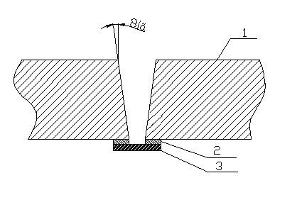
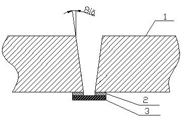
[0033] like figure 1 The example of ordinary submerged arc welding is shown. Before rolling on both sides of the air bag plate, a V-shaped groove of 8 degrees on one side is processed on the groove machine, and a bottom gap of 20-24mm is formed after rolling. , a V-groove with an opening angle of 16 degrees. Then use manual arc welding to fix the first layer of liner (the same material as the base metal) on both sides of the groove. Small standard welding parameters should be used during manual arc welding to prevent undercut defects on both sides of the base metal. After the first layer of liner is fixed, weld and fix the second layer of liner (material of ordinary carbon steel 20#) on the first layer of liner. After the double-layer liner is fixed, the entire weld can be welded according to the requirements of the welding procedure instruction. After the welding of the entire weld seam is completed, a part of the double liner can be cut off by flame cutting, and a residua...

Embodiment 2

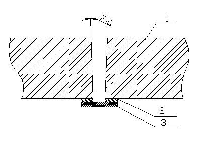
[0035] like figure 2 In the example shown when narrow gap submerged arc automatic welding is used, before rolling both sides of the air bag plate, a single side 2 degree, root gap is 18 ~ 20mm, and the opening angle is 4 degrees V on the beveling machine. type groove. The material of the first layer of gasket is the same as that of the parent material; the material of the second layer of gasket is ordinary carbon steel Q235A. All the other are with embodiment 1.


PUM


Abstract

The invention relates to thick metal plate back gouging-free welding groove technology. The technology is characterized in that: a welding groove consists of a substrate V-shaped groove and two layers of gaskets connected to the lower surface of the substrate V-shaped groove. A welding process comprises the following steps of: before the two sides of a substrate are rolled, machining a single-sided 2 to 10-degree V-shaped groove on a facing machine, and after the two sides of the substrate are rolled and molded, forming the V-shaped groove with the bottom gap of 16 to 26 mm and the opening of4 to 20 degrees; fixing a first layer of gasket on the two sides of the groove by arc welding; fixing a second layer of gasket on the first layer of gasket by welding; welding an entire welding line according to the requirements of a welding process instruction; chopping a part of the two layers of gaskets by adopting a flame cutting method to keep the weld reinforcement of 3 to 5 mm; and grinding the weld reinforcement off by adopting a grinding wheel machine. In the technology and the welding process, the welding line is molded once, the times of preheating, dehydrogenation and flaw detection are reduced in the welding process, the manufacturing cost is saved and a manufacturing cycle is shortened.

Description

technical field [0001] The invention relates to a welding technology, in particular to a pressure vessel thick plate with liner submerged arc automatic welding without root cleaning welding groove technology. Background technique [0002] In the prior art, in the welding of thick metal plates of boilers and pressure vessels, there are roughly four types of welding grooves: 1) V-shaped groove with liner; 2) U-shaped groove; 3) double U-shaped groove ; 4) U+V groove. The disadvantage of the prior art is that no matter which one of the above four bevel forms is used, after the welding on one side is completed, before the other side is welded, it is necessary to use carbon arc gouging to clean the root, and then use a grinding wheel to clean the root. polished. If the grinding wheel is not thoroughly ground, the carburized layer produced by carbon arc gouging during the root cleaning process is likely to have adverse effects on the weld and the base metal. At the same time, i...

Claims


Application Information

Patent Timeline
IPC IPC(8): B23K33/00B23K9/02B23K9/235
Inventor 汪志明李建强姜龙卢伟
Owner HANGZHOU BOILER GRP CO LTD
Learn More