Process for depositing organic materials

一种沉积装置、有机薄膜的技术,应用在金属材料涂层工艺、对表面涂布液体的装置、涂层等方向

Inactive Publication Date: 2011-04-20
EASTMAN KODAK CO
View PDF9 Cites 28 Cited by
  • Summary
  • Abstract
  • Description
  • Claims
  • Application Information

AI Technical Summary

Problems solved by technology

For example, it is difficult to maintain uniform vacuum at different points in the array and synchronize gas flow and vacuum at complementary pressures, thus sacrificing the uniformity of gas flow provided to the substrate surface

Method used


Image

  • Process for depositing organic materials
  • Process for depositing organic materials
  • Process for depositing organic materials

Examples


Embodiment 1

[0134] Alucone, preparation of an organic-containing thin film

[0135] This example describes the preparation of alucone, a thin film containing a significant amount of organic material. For this deposition, bubbler 82 contained trimethylaluminum as the O2 precursor and bubbler 84 contained ethylene glycol as the O1 precursor.

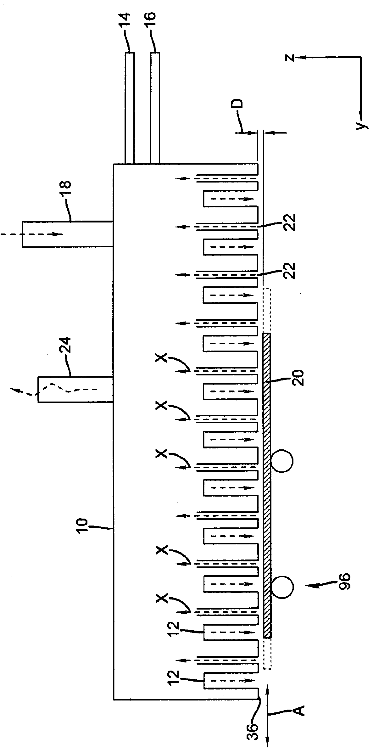
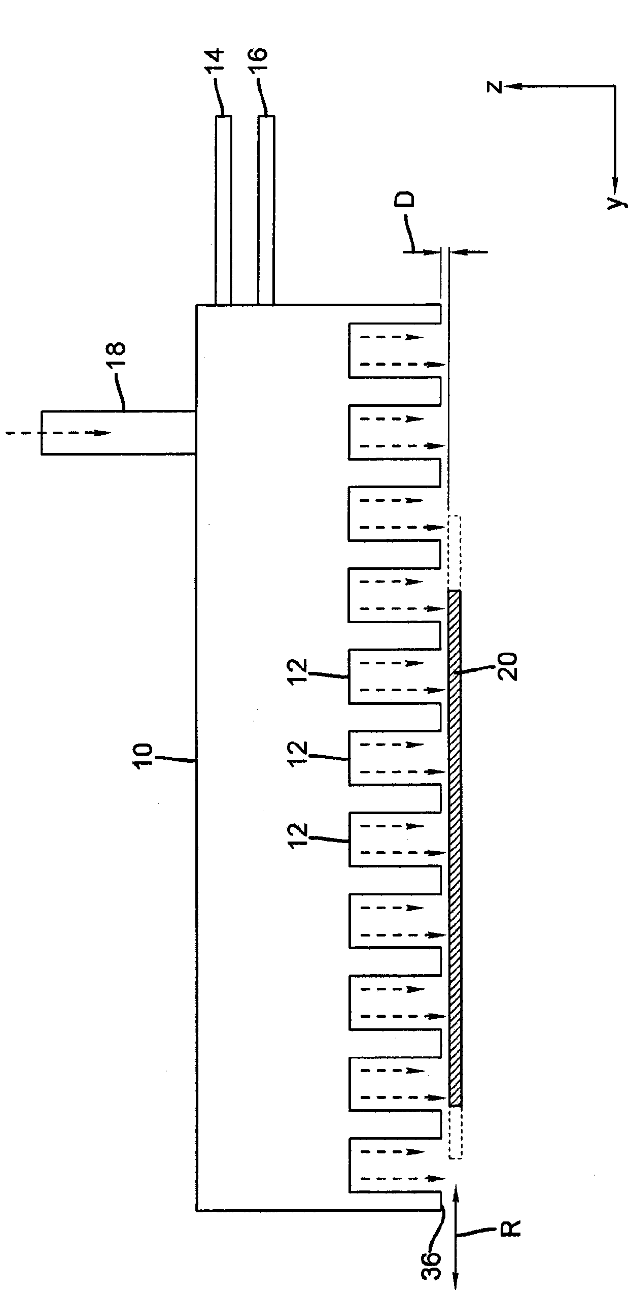
[0136] A 2.5 x 2.5 inch square (62.5 mm square) silicon wafer was placed on the platen of the apparatus, held in place by a vacuum and heated to 200°C. The platen with the substrate is positioned below the coating head directing the flow of reactive gas. The distance between the silicon substrate and the coating head was adjusted to 30 microns using a micrometer.

[0137] The applicator head was maintained at 40°C. The flow rate of a single gas, shown in Table 1 below, caused the coating head to vibrate across the substrate for the specified number of cycles to initiate the coating process.

[0138] Table 1

[0139] sample

flow ...

Embodiment 2

[0143] Preparation of Borcone

[0144] Borocone can be formed using ALD or molecular layer epitaxy. This hypothetical example describes the preparation of borocone, a thin film containing a significant amount of organic material. For this deposition, bubbler 82 contained trimethyl borate, B(OMe) as O precursor 3 , bubbler 84 contains ethylene glycol as O1 precursor.

[0145] The apparatus used for the preparation of borocone was the same as that described in Example 1. A 2.5 x 2.5 inch square (62.5 mm square) silicon wafer was placed on the platen of the apparatus, held in place by a vacuum and heated to 200°C. The platen with the substrate is positioned below the coating head directing the reactive gas flow. The distance between the silicon substrate and the coating head was adjusted to 30 microns using a micrometer.

[0146] The applicator head was maintained at 40°C. The substrate was maintained at 30°C-250°C. The desired borocone thickness can be obtained by contr...

Embodiment 3

[0151] Preparation of polyurethane

[0152] In another hypothetical embodiment of the present invention, polyurethane thin films can be formed using ALD or molecular layer epitaxy. This example describes the preparation of a polyurethane film, a thin film containing a substantial amount of organic material. For this deposition, bubbler 82 contained 1,4-butanediol as the O2 precursor and bubbler 84 contained 1,4-diisocyanatobutane as the O1 precursor.

[0153] The apparatus used to prepare polyurethane films was the same as that described in Example 1. A 2.5 x 2.5 in2 (62.5 mm2) silicon plate was placed on the platen of the apparatus, held in place by vacuum and heated to 200°C. The platen with the substrate is positioned below the coating head for directing the reactive gas flow. The distance between the silicon substrate and the coating head was adjusted to 30 microns using a micrometer.

[0154] The temperature of the applicator head was maintained at 40°C. The substr...


PUM


Abstract

A process of making an organic thin film on a substrate by atomic layer deposition is disclosed, the process comprising simultaneously directing a series of gas flows along substantially parallel elongated channels, and wherein the series of gas flows comprises, in order, at least a first reactive gaseous material, an inert purge gas, and a second reactive gaseous material, optionally repeated a plurality of times, wherein the first reactive gaseous material is capable of reacting with a substrate surface treated with the second reactive gaseous material wherein the first reactive gaseous material, the second reactive gaseous material or both is a volatile organic compound. The process is carried out substantially at or above atmospheric pressure and at a temperature under 250 DEG C, during deposition of the organic thin film.

Description

field of invention [0001] The present invention relates generally to thin organic films and, more particularly, to a method of depositing organic thin films on substrates using atomic or molecular layer deposition. In particular, the present invention relates to a method of preparing organic thin films, including inorganic-organic hybrid thin films, which may be used in electronic or optical devices. Background of the invention [0002] Modern electronic devices require patterned layers of electrically or optically active materials, often deposited on relatively large substrates. Electronic devices such as radio frequency identification (RFID) tags, photovoltaic devices, optical and chemical sensors all require some degree of patterning in their electronic circuitry. Flat panel displays, such as liquid crystal displays or electroluminescent displays (excluding OLEDs) rely on a precise patterning of sequential layers to form the thin film elements of the backplane. These el...

Claims


Application Information

Patent Timeline
Patent Type & Authority Applications(China)
IPC IPC(8): H01L31/18H01L51/50B05D7/24C23C16/455C23C16/30
CPCC23C16/545C23C16/45553C23C16/45551B05D2252/02B05D1/60C23C16/30
Inventor D·C·弗里曼D·H·莱维P·J·考德里-科尔文
Owner EASTMAN KODAK CO
Why Eureka
Try Eureka