Thermodynamic cycle system for a vehicle

A technology of circulation system and moving body, applied in the field of thermal circulation system, can solve the problems of cooling medium temperature reduction, etc., and achieve the effect of improving energy saving effect

Inactive Publication Date: 2011-04-27
HITACHI LTD
View PDF6 Cites 17 Cited by
  • Summary
  • Abstract
  • Description
  • Claims
  • Application Information

AI Technical Summary

Problems solved by technology

However, in the heat exchange between the air and the cooling medium, since the temperature of the cooling medium cannot be lowered below the air temperature, for example, when the heat generation (temperature) of the heat generating component is large in summer, it is difficult to reduce the heat generation. The temperature of the component is close to the proper temperature at which the heat-generating component can work efficiently

Method used


Image

  • Thermodynamic cycle system for a vehicle
  • Thermodynamic cycle system for a vehicle
  • Thermodynamic cycle system for a vehicle

Examples


Embodiment 1

[0095] use Figure 1 to Figure 8 The first example of the thermal cycle system installed in EV1000 will be described.

[0096] Figure 1 to Figure 8 Shows the configuration of the thermal cycle system installed in the EV1000.

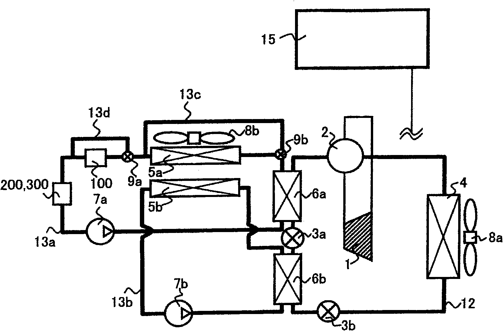
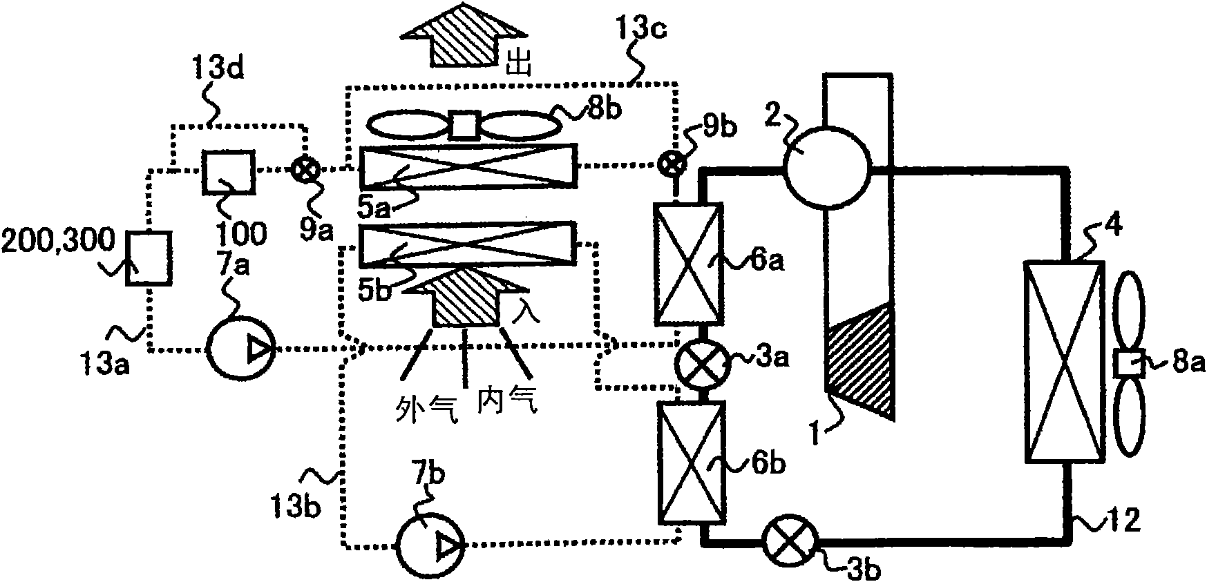
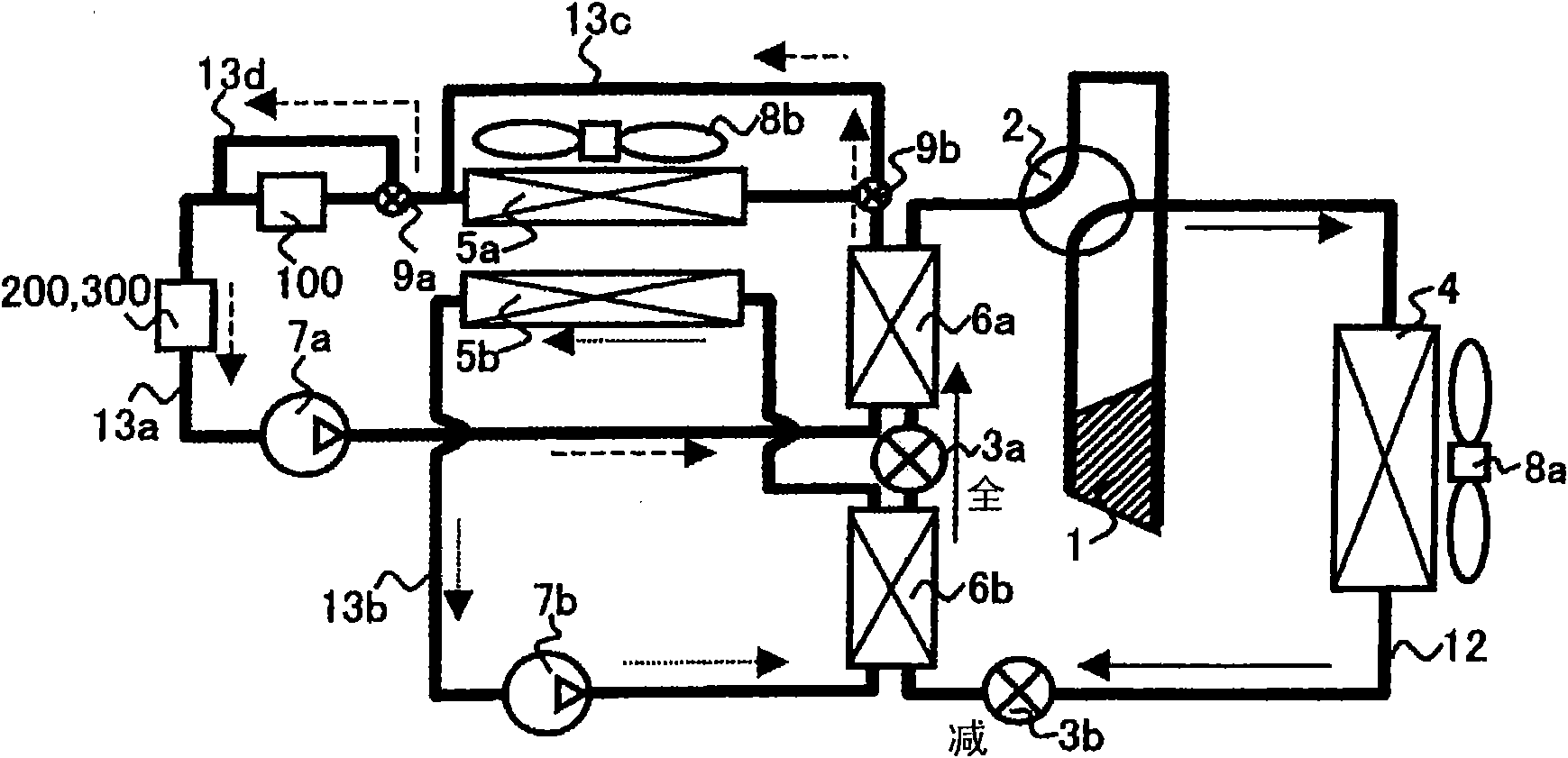
[0097] In addition, in figure 2 In the diagram, the coolant piping 12 (primary side heat cycle circuit) through which refrigerant such as HFC-134a flows is indicated by a solid line. Dotted lines indicate heat transfer medium pipes 13 a and 13 b (secondary heat circulation circuit) through which a liquid coolant (heat transfer medium) such as water or antifreeze flows.

[0098] The thermal cycle system equipped with EV1000 such as figure 1 , figure 2 As shown, the heat cycle circuit is divided into a primary side heat cycle circuit that exchanges heat with the outdoor side, and a secondary side heat cycle circuit that performs heat exchange with the indoor side and the heat-generating component side. The primary side thermal cycle loop consists ...

Embodiment 2

[0146] use Figure 9 as well as Figure 10 The second example of the thermal cycle system installed in EV1000 will be described.

[0147] This embodiment is a modified example of the first embodiment, and the correspondence relationship between the intermediate heat exchangers 6a, 6b and the first and second heat transfer systems is opposite to that of the first embodiment. That is to say, through the intermediate heat exchanger 6b arranged between the decompressors 3a and 3b, the coolant in the first heat transfer system and the refrigerant in the refrigeration cycle system are heat-exchanged, The intermediate heat exchanger 6a between the four-way valves 2 exchanges heat between the coolant in the second heat transfer system and the refrigerant in the refrigeration cycle system.

[0148] Since other structures are the same as those of the first embodiment, the same symbols as those of the first embodiment are attached to the same structures as those of the first embodiment...

Embodiment 3

[0152] use Figure 11 The third example of the thermal cycle system installed in EV1000 will be described.

[0153] This embodiment is an improved example of the second embodiment. In this embodiment, an outdoor heat exchanger 14 is provided on the bypass pipe 13c. The outdoor heat exchanger 14 is arranged on the upstream side of the outdoor heat exchanger 4 with respect to the air flow sent by the fan 8a, so that it is arranged side by side with the outdoor heat exchanger 4, so that the air sent by the fan 8a can flow through the bypass pipe 13c coolant for heat exchange. In addition, in this embodiment, the three-way valve 9b is arranged between the pump 7a and the intermediate heat exchanger 6b. Thereby, the coolant before heat exchange by the intermediate heat exchanger 6b can flow through the bypass pipe 13c.

[0154] Since other structures are the same as those of the second embodiment, the same symbols as those of the second embodiment are attached to the same struc...


PUM


Abstract

A thermodynamic cycle system for a moving vehicle, including a refrigeration cycle system through which a refrigerant flows, a first heat-transferring system through which a heat-transferring medium flows, the heat-transferring medium being used for adjusting temperatures of heat-liberation components, a second heat-transferring system through which a heat-transferring medium flows, the heat-transferring medium being used for adjusting an indoor air state, an intermediate heat exchanger (6a) provided between the refrigeration cycle system and the first heat-transferring system, an intermediate heat exchanger (6b) provided between the refrigeration cycle system and the second heat-transferring system, an indoor heat exchanger (5a) provided in the first heat-transferring system, and an indoor heat exchanger (5b) provided in the second heat-transferring system.

Description

technical field [0001] The present invention relates to a thermal cycle system mounted on a mobile body. Background technique [0002] As the background art related to the thermal cycle system mounted on a mobile body, there are, for example, the technologies shown in Patent Documents 1 and 2 . Patent Document 1 discloses a technique in which a heater is provided in a refrigeration cycle system, and heat generated by a heating cycle of the refrigeration cycle and heat generated by an electric heater are used to provide heating capacity. Patent Document 2 discloses a technology in which a cooling fluid that receives heat emitted by a heat-generating component exchanges heat with a refrigerant in a refrigeration cycle, and effectively utilizes the heat emitted by the heat-generating component as a heat source during heating operation of the refrigeration cycle. to increase heating capacity. [0003] Patent Document 1: Japanese Patent Laid-Open No. 2008-230594 [0004] Paten...

Claims


Application Information

Patent Timeline
Patent Type & Authority Applications(China)
IPC IPC(8): B60H1/22F25B13/00F25B29/00
CPCB60H1/00278B60H2001/00928B60H1/00392Y02T10/88B60H2001/00307B60L1/003B60L2200/18B60L2200/36B60L2240/34B60L2240/36B60L2240/425B60L2240/525B60L2240/545B60L58/26B60L58/27B60H1/32281Y02T10/64Y02T10/70
Inventor 荒井雅嗣奈须真吾松岛弘章小谷正直小松智弘关谷祯夫
Owner HITACHI LTD
Why Eureka
Try Eureka