Thermo-acoustic process testing system and testing method

A process testing and thermoacoustic technology, applied in the fields of thermodynamics, fluid mechanics and acoustics, which can solve the problems such as the inability to measure the temperature field and the sound field synchronously, the measurement results unable to truly reflect the thermoacoustic process, and the inability to respond to the instantaneous changes of gas micelles.

Inactive Publication Date: 2011-05-04
TECHNICAL INST OF PHYSICS & CHEMISTRY - CHINESE ACAD OF SCI
View PDF0 Cites 19 Cited by
  • Summary
  • Abstract
  • Description
  • Claims
  • Application Information

AI Technical Summary

Problems solved by technology

However, in the prior art, due to the limitation of the tracer technology, the MicroPIV of the prior art is only used to measure the liquid working medium with low-speed directional flow
The thermoacoustic heat engine uses gas working fluids such as nitrogen and helium, and these gas working fluids work in an alternating fluctuating state. The measurement technology of the liquid flow field cannot reflect the instantaneous changes of the gas microgroups in the thermoacoustic heat engine.
[0007] More importantly, the same thermoacoustic core can realize different thermodynamic cycles in different sound fields, and the existing technology cannot measure the temperature field and sound field simultaneously, so it cannot reflect the interaction between the temperature field and the sound field in the thermoacoustic process. coupling effect, the measurement results cannot truly reflect the actual thermoacoustic process

Method used


Image

  • Thermo-acoustic process testing system and testing method
  • Thermo-acoustic process testing system and testing method
  • Thermo-acoustic process testing system and testing method

Examples


Embodiment 1

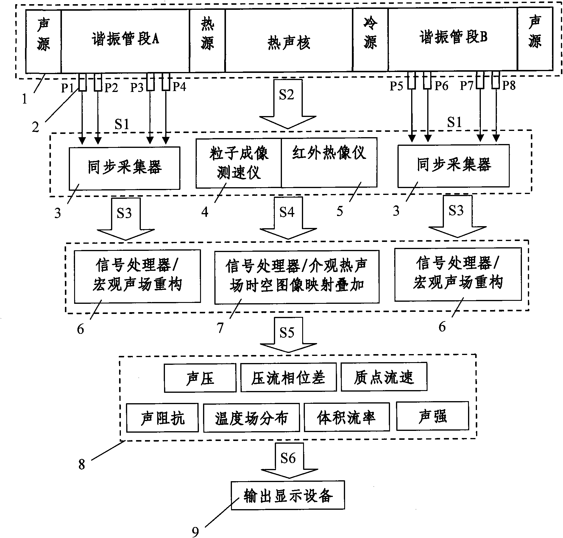
[0086] refer to figure 1, according to Embodiment 1, the thermoacoustic testing system includes a macroscopic sound field modulation unit 1, a flow field measurement window (not shown in the figure), a temperature field measurement window (not shown in the figure), a microscale particle imaging velocimeter 4 (MicroPIV ), an infrared thermal imager 5 and a spatio-temporal image mapping superposition unit 7.

[0087] Among them, the macroscopic sound field modulation unit includes an opposed sound source, a resonant pipe section A, a heat source, a cold source and a resonant pipe section B, which are assembled with a thermoacoustic core to form a thermoacoustic heat engine. In particular, if the thermoacoustic core to be tested has been installed in a thermoacoustic heat engine, the macroscopic sound field modulation unit of this embodiment can directly use the corresponding components in the thermoacoustic heat engine. Similarly, other embodiments of the present invention may ...

Embodiment 2

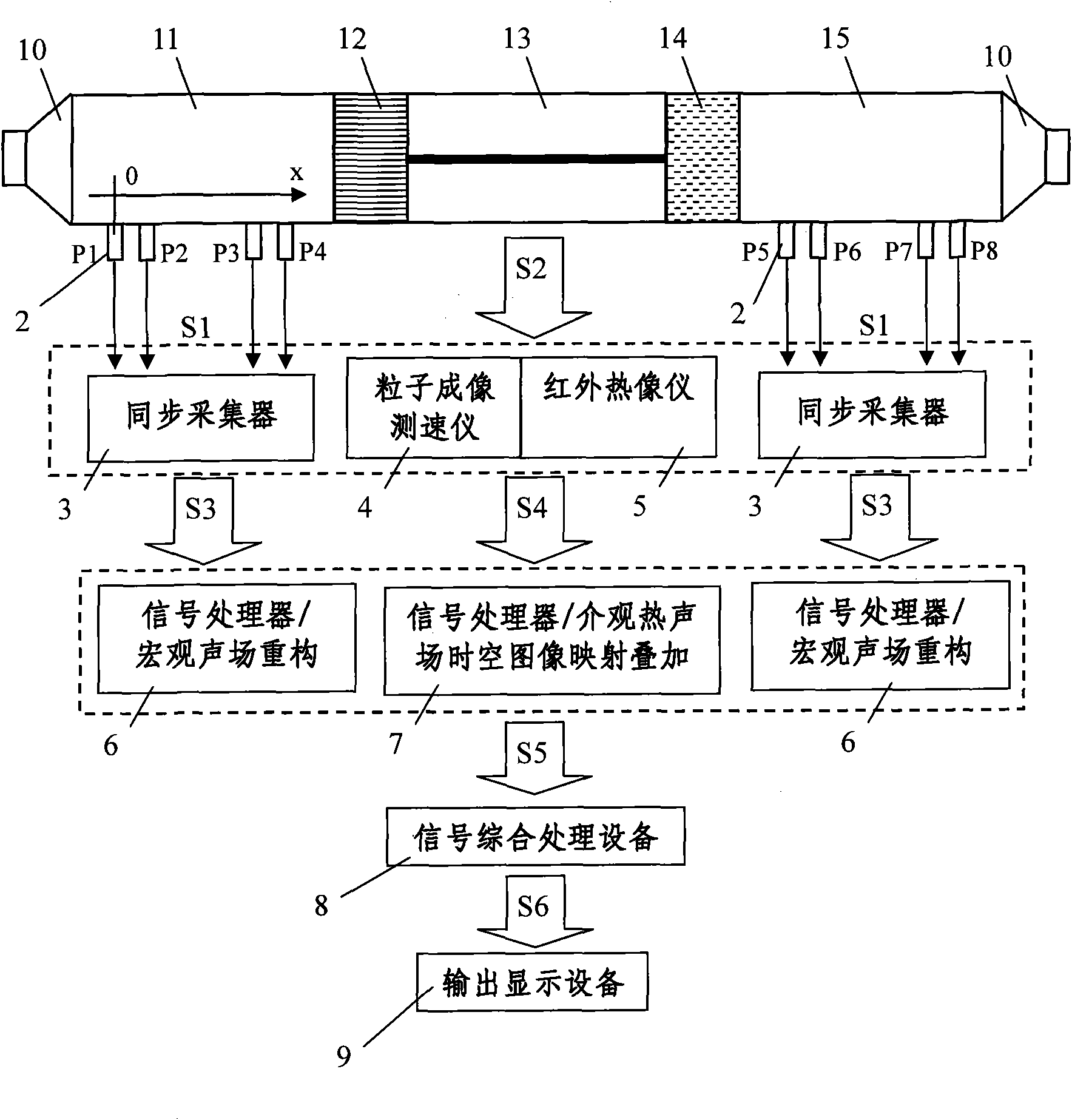
[0092] figure 2 Shown is an exemplary embodiment of the invention for use in an opposed loudspeaker driven thermoacoustic system. The opposing loudspeaker-driven thermoacoustic system shown consists of a loudspeaker 10 , a resonant pipe section 11 , a hot end heat exchanger 12 , a thermoacoustic core 13 , a cold end heat exchanger 14 (also called a room temperature heat exchanger) and a resonant pipe section 15 . The thermoacoustic system relies on the sound work generated by the speakers opposed at both ends to drive the movement of the gas working medium in the thermoacoustic system.

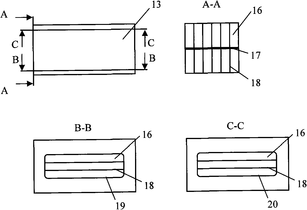
[0093] image 3 Shown is a schematic diagram of the structure of a thermoacoustic core in an opposed loudspeaker driven thermoacoustic system. As shown in the figure, the thermoacoustic core 13 is composed of an airway space 16 , a partition 17 , a flat plate 18 , quartz glass 19 and a zinc sulfide crystal 20 . When performing mesoscopic measurements on the thermoacoustic core, the infrare...

Embodiment 3

[0133] Figure 10 It is a schematic diagram of an embodiment of the present invention applied to a thermoacoustic refrigerator driven by a 1 / 4 wavelength single speaker. The shown 1 / 4 wavelength thermoacoustic refrigerator is composed of a speaker 10 , a resonant pipe section 11 , a room temperature heat exchanger 14 , a thermoacoustic core 13 , a cold head 21 and a resonant pipe section 15 . The thermoacoustic refrigerator is driven by a loudspeaker, and emits sound work to drive the gas working fluid in the thermoacoustic system to produce a cooling effect on the cold head 21 . Such as Figure 10 As shown, a single loudspeaker 10 is arranged at one end of the thermoacoustic system to modulate the sound field at both ends of the thermoacoustic core so that it is under the sound field conditions of stable frequency, stable amplitude and stable phase angle. A hot end heat exchanger 12 and a cold end heat exchanger 14 are arranged at both ends of the thermoacoustic core 13, an...


PUM


Abstract

The invention provides a thermo-acoustic process testing system and a thermo-acoustic process testing method. The testing system comprises an acoustic field modulation unit, a flow field measurement window, a temperature field measurement window, a micro-scale particle imaging speedometer, a thermal infrared imager and a time-space image mapping and superposing unit. The testing method comprises the following steps of: 1) generating temperature fields, and acoustic fields with stable frequencies, amplitudes and phase angles at the two ends of a thermo-acoustic core; 2) measuring flow field distribution in the thermo-acoustic core at a series of sampling time points tc; 3) measuring a temperature field distribution process along with time variation in the thermo-acoustic core; 4) equivalently converting the flow field distribution at each sample time point tc into the flow field distribution at a virtual sampling time point tc' in the same period T of an acoustic field according to a sampling time point serial number; and 5) acquiring the correspondence between the flow field distribution and the temperature field distribution along with time variation. By the system and the method, the temperature fields and the acoustic fields in the thermo-acoustic core can be synchronously measured, and a measurement result really reflects an actual thermo-acoustic process.

Description

technical field [0001] The invention relates to the technical fields of thermodynamics, fluid mechanics and acoustics, in particular, the invention relates to a thermoacoustic testing system and testing method for thermoacoustic heat engines. Background technique [0002] Thermoacoustic heat engine is a new type of high-efficiency heat engine. It uses the thermoacoustic phenomenon in physics to make the working gas complete the thermodynamic microcirculation on the mesoscopic level in the microstructure channel of the thermoacoustic element, and directly realize the heat energy to sound energy (mechanical energy) mutual conversion. The entire heat engine system is only the oscillation of the gas working medium itself, without any moving parts, the system is simple, there are no moving parts, and there is no life limit in principle. Thermoacoustic heat engines have brought about a revolution in heat engines. Thermoacoustics is the intersection of heat and acoustics. It is ne...

Claims


Application Information

Patent Timeline
Patent Type & Authority Applications(China)
IPC IPC(8): G01D21/00G01H17/00G01P5/20G01J5/10
Inventor 李青谢秀娟李正宇
Owner TECHNICAL INST OF PHYSICS & CHEMISTRY - CHINESE ACAD OF SCI
Why Eureka
Try Eureka