
System and method for automatically acquiring and analyzing trace gas

A gas collection and automatic collection technology, applied in the field of soil and low vegetation measurement, can solve problems such as difficulty in research, inability to obtain long-term synchronous observation of carbon and nitrogen trace gases in situ, large errors, etc.

Inactive Publication Date: 2011-05-11
INST OF ATMOSPHERIC PHYSICS CHINESE ACADEMY SCI
View PDF0 Cites 24 Cited by
  • Summary
  • Abstract
  • Description
  • Claims
  • Application Information

AI Technical Summary

Problems solved by technology

It is due to the unavoidable large error caused by low-frequency observations that for N 2 It is very difficult to study the O emission process and its control mechanism of environmental factors
Existing manual observation techniques cannot obtain in situ effective long-term synchronous observation data of carbon and nitrogen trace gases, and existing in situ observation techniques can only measure CH 4 and N 2 For the determination of these two components, it is urgent to develop in-situ automatic observation technology to measure various carbon and nitrogen components (CH 4 , CO 2 , N 2 O, NO) at the same time to study the terrestrial ecosystem-atmospheric carbon and nitrogen trace gas exchange process, law and mechanism, to obtain the measured data and parameters to verify the model, and to evaluate the effectiveness of ecosystem greenhouse gas emission reduction measures

Method used


Image

  • System and method for automatically acquiring and analyzing trace gas
  • System and method for automatically acquiring and analyzing trace gas
  • System and method for automatically acquiring and analyzing trace gas

Examples


Embodiment Construction

[0039] The present invention will be described in further detail below in conjunction with accompanying drawing and embodiment:

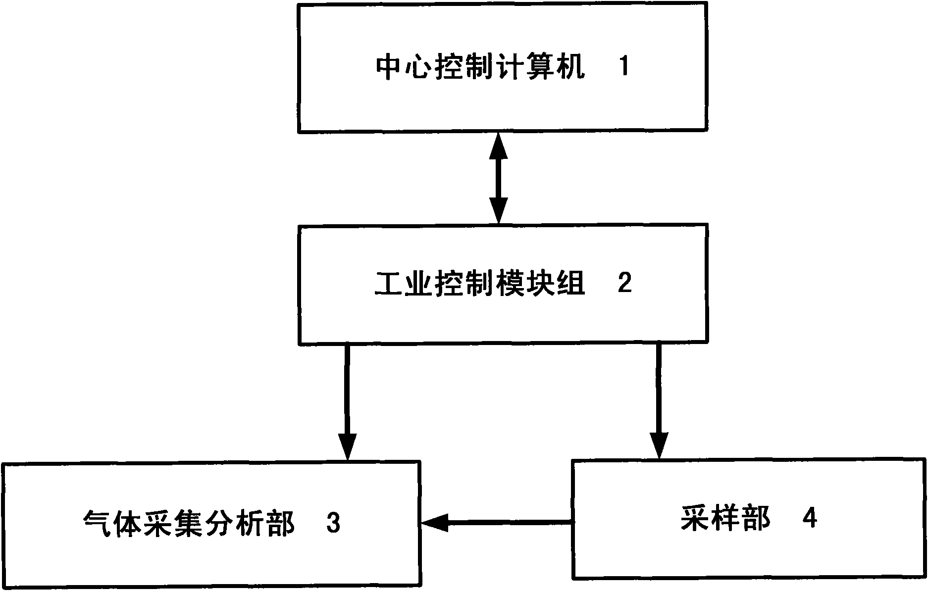
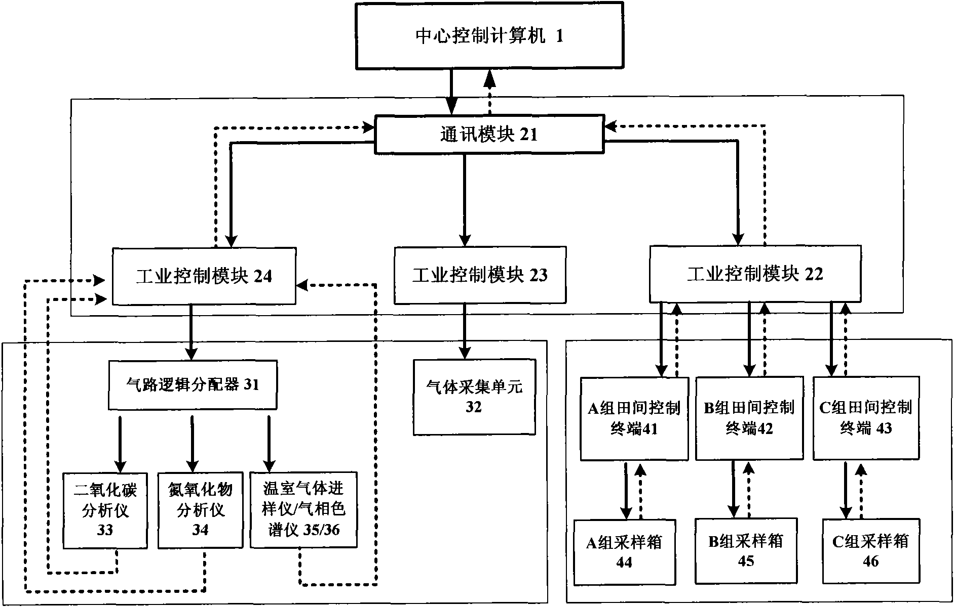
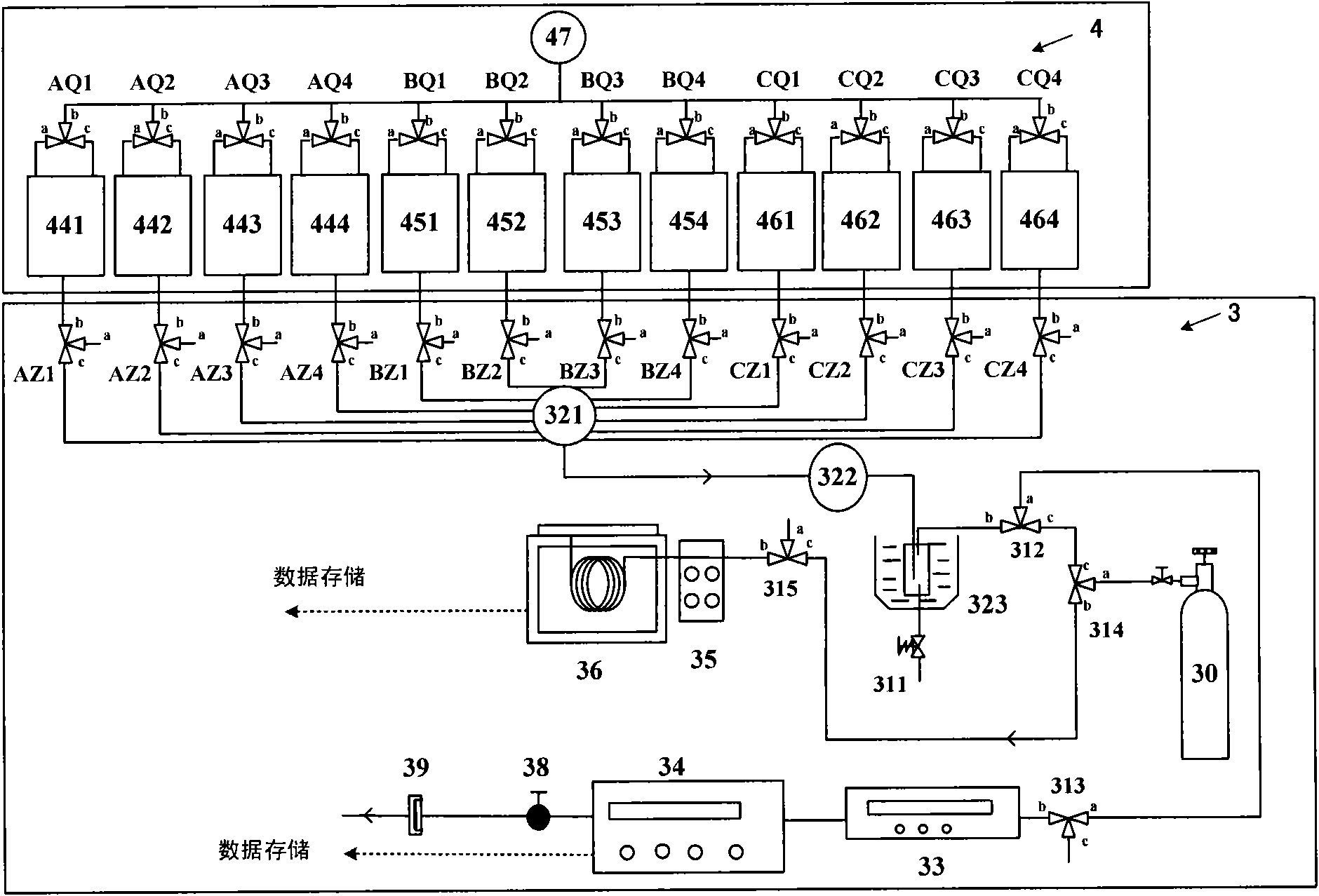
[0040] figure 1 Shows the overall block diagram of the trace gas automatic observation system, which is composed of a central control computer 1, an industrial control module group 2, a gas collection and analysis part 3 and a sampling part 4, wherein:

[0041] The central control computer 1 is an industrial control computer, which is connected with the industrial control module group 2 through the RS232 interface, writes a program through the industrial control configuration software in the central control computer 1, and generates and sends the industrial control command, gas path and Industrial control instructions for gas collection and analysis; receive and store analog signals containing environmental meteorological parameters and trace gas concentration data sent by industrial control module group 2;

[0042]The industrial control module gro...


PUM


Abstract

The invention relates to a system for automatically acquiring and analyzing a trace gas, which comprises a central control computer, an industrial control module group, a sampling part and a gas acquisition and analysis part, wherein the central control computer is used for writing programs by means of industrial control configuration software, generating and transmitting tank cover, gas passage and gas analysis commands, and receiving and storing analog signals which contain environmental meteorologic parameters and trace gas concentration data and are transmitted by the industrial control module group; the industrial control module group is respectively connected with the central control computer, the sampling part and the gas acquisition and analysis part; the gas acquisition and analysis part is connected with a pipeline of the sampling part; the industrial control module group is used for receiving industrial control commands, outputting multiple switching signals, and controlling the sampling part and the gas acquisition and analysis part to automatically carry out tank cover switching, gas acquisition and trace gas concentration analysis according to the programs; and the industrial control module group is used for processing current signals output by the sampling part and voltage signals output by the gas acquisition and analysis part and outputting the analog signals containing the environmental meteorologic parameters and the gas concentration data.

Description

technical field [0001] The invention belongs to the measurement of soil and low vegetation (methane, carbon dioxide, nitrous oxide and nitric oxide), and relates to an automatic collection and analysis system and method for trace gases. Background technique [0002] In the past century, the global climate change caused by the increase in the concentration of greenhouse gases such as carbon dioxide, methane and nitrous oxide in the atmosphere has had a major impact on the world's economy, society and ecological environment, and has seriously threatened the sustainable development of the economy and the national economy. Safety. Soil is the main source of trace gases in the atmosphere, especially agricultural activities relying on soil, especially atmospheric CH 4 , CO 2 , N 2 An important source of trace gases such as O and NO. Estimates of the sources of these trace gases, which have important contributions to the greenhouse effect and atmospheric chemistry, remain subje...

Claims


Application Information

Patent Timeline
IPC IPC(8): G01N35/00G01N1/24G01N30/02G05B19/418
CPCY02P90/02
Inventor 刘广仁王迎红王跃思刘春岩郑循华
Owner INST OF ATMOSPHERIC PHYSICS CHINESE ACADEMY SCI
Learn More